Safety
information
Product
information
Mechanical
installation
Electrical
installation
Getting
started
Basic
parameters
Running
the motor
Optimization
NV Media Card
Operation
Onboard
PLC
Advanced
parameters
Technical
data
Diagnostics
UL listing
information
76 Unidrive M702 User Guide
Issue Number: 3
Unshielded wiring to the optional braking resistor(s) may be used
provided the wiring runs internally to the enclosure. Ensure a minimum
spacing of 300 mm (12 in) from the signal wiring and the AC supply
wiring to the external EMC filter. If this condition cannot be met then the
wiring must be shielded.
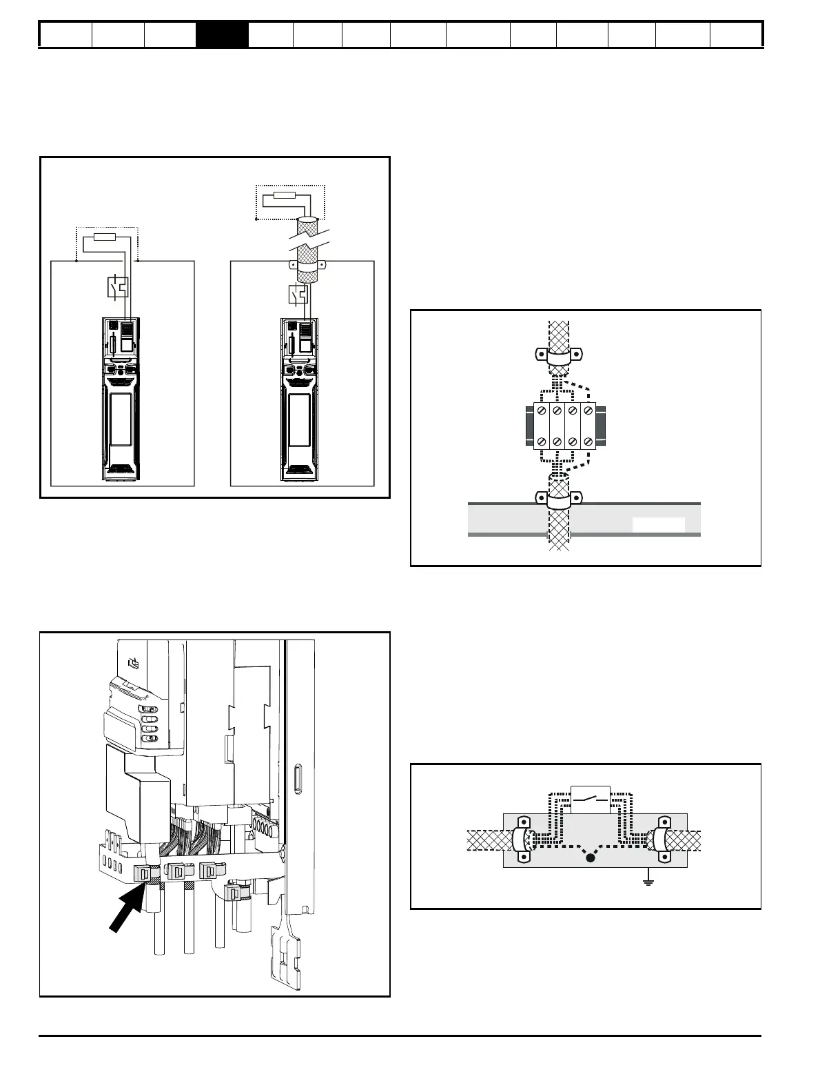
Figure 4-37 Shielding requirements of optional external braking
resistor
If the control wiring is to leave the enclosure, it must be shielded and the
shield(s) clamped to the drive using the grounding bracket as shown in
Figure 4-38. Remove the outer insulating cover of the cable to ensure
the shield(s) make direct contact with the bracket, but keep the shield(s)
intact until as close as possible to the terminals
Alternatively, wiring may be passed through a ferrite ring, part number
3225-1004.
Figure 4-38 Grounding of signal cable shields using the
grounding bracket
4.12.6 Variations in the EMC wiring
Interruptions to the motor cable
The motor cable should ideally be a single length of shielded or armored
cable having no interruptions. In some situations it may be necessary to
interrupt the cable, as in the following examples:
• Connecting the motor cable to a terminal block in the drive enclosure
• Installing a motor isolator / disconnect switch for safety when work is
done on the motor
In these cases the following guidelines should be followed.
Terminal block in the enclosure
The motor cable shields should be bonded to the back-plate using
uninsulated metal cable-clamps which should be positioned as close as
possible to the terminal block. Keep the length of power conductors to a
minimum and ensure that all sensitive equipment and circuits are at
least 0.3 m (12 in) away from the terminal block.
Figure 4-39 Connecting the motor cable to a terminal block in the
enclosure
Using a motor isolator / disconnect-switch
The motor cable shields should be connected by a very short conductor
having a low inductance. The use of a flat metal coupling-bar is
recommended; conventional wire is not suitable.
The shields should be bonded directly to the coupling-bar using
uninsulated metal cable-clamps. Keep the length of the exposed power
conductors to a minimum and ensure that all sensitive equipment and
circuits are at least 0.3 m (12 in) away.
The coupling-bar may be grounded to a known low-impedance ground
nearby, for example a large metallic structure which is connected closely
to the drive ground.
Figure 4-40 Connecting the motor cable to an isolator /
disconnect switch
Surge immunity of control circuits - long cables and
connections outside a building
The input/output ports for the control circuits are designed for general
use within machines and small systems without any special precautions.
These circuits meet the requirements of EN 61000-6-2:2005 (1 kV
surge) provided the 0 V connection is not grounded.
+DC
BR
Optional external
braking resistor
Enclosure
+DC
BR
Optional external
braking resistor
Enclosure
OR
Isolator
Coupling bar
From the
Drive
To the
motor

 Loading...


