Safety
information
Product
information
Mechanical
installation
Electrical
installation
Getting
started
Basic
parameters
Running
the motor
Optimization
NV Media Card
Operation
Onboard
PLC
Advanced
parameters
Technical
data
Diagnostics
UL listing
information
Unidrive M702 User Guide 67
Issue Number: 3
4.10.2 External braking resistor
When a braking resistor is to be mounted outside the enclosure, ensure
that it is mounted in a ventilated metal housing that will perform the
following functions:
• Prevent inadvertent contact with the resistor
• Allow adequate ventilation for the resistor
When compliance with EMC emission standards is required, external
connection requires the cable to be armored or shielded, since it is not
fully contained in a metal enclosure. See section 4.12.5 Compliance with
generic emission standards on page 74 for further details.Internal
connection does not require the cable to be armored or shielded.
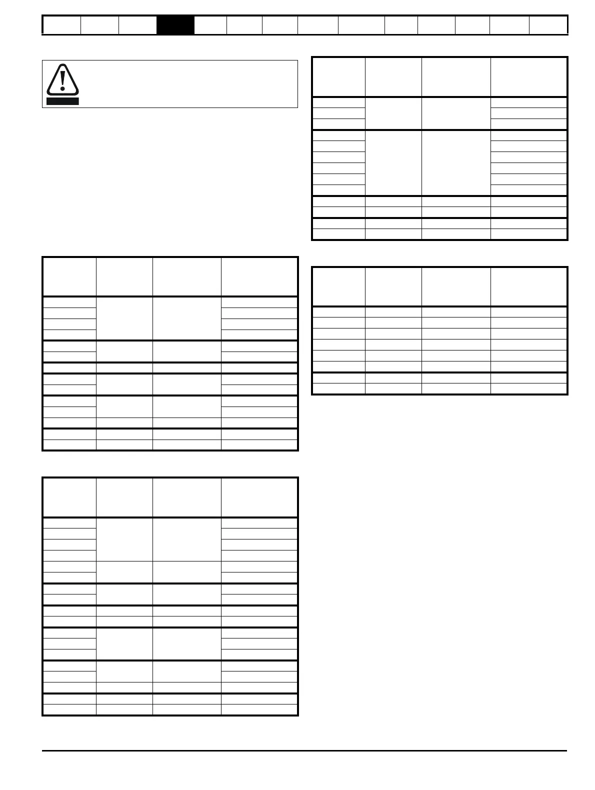
Minimum resistances and power ratings for the braking
resistor at 40 °C (104 °F)
Table 4-19 Braking resistor resistance and power rating (200 V)
Table 4-20 Braking resistor resistance and power rating (400 V)
Table 4-21 Braking resistor resistance and power rating (575 V)
Table 4-22 Braking resistor resistance and power rating (690 V)*
* Resistor tolerance: ±10 %
For high-inertia loads or under continuous braking, the continuous power
dissipated in the braking resistor may be as high as the power rating of
the drive. The total energy dissipated in the braking resistor is dependent
on the amount of energy to be extracted from the load.
The instantaneous power rating refers to the short-term maximum power
dissipated during the on intervals of the pulse width modulated braking
control cycle. The braking resistor must be able to withstand this
dissipation for short intervals (milliseconds). Higher resistance values
require proportionately lower instantaneous power ratings.
In most applications, braking occurs only occasionally. This allows the
continuous power rating of the braking resistor to be much lower than
the power rating of the drive. It is therefore essential that the
instantaneous power rating and energy rating of the braking resistor are
sufficient for the most extreme braking duty that is likely to be
encountered.
Optimization of the braking resistor requires careful consideration of the
braking duty.
Select a value of resistance for the braking resistor that is not less than
the specified minimum resistance. Larger resistance values may give a
cost saving, as well as a safety benefit in the event of a fault in the
braking system. Braking capability will then be reduced, which could
cause the drive to trip during braking if the value chosen is too large.
Thermal protection circuit for the braking resistor
The thermal protection circuit must disconnect the AC supply from the
drive if the resistor becomes overloaded due to a fault. Figure 4-18
shows a typical circuit arrangement.
Overload protection
When an external braking resistor is used, it is essential that
an overload protection device is incorporated in the braking
resistor circuit; this is described in Figure 4-18 on page 68.
Model
Minimum
resistance *
Instantaneous
power rating
Continuous
power rating
Ω kW kW
03200050
20 8.5
1.5
03200066 1.9
03200080 2.8
03200106 3.6
04200137
18 9.4
4.6
04200185 6.3
05200250 16.5 10.3 8.6
06200330
8.6 19.7
12.6
06200440 16.4
07200610
6.1 27.8
20.5
07200750 24.4
07200830 4.5 37.6 32.5
08201160
08201320
Model
Minimum
resistance *
Instantaneous
power rating
Continuous
power rating
Ω kW kW
03400025
74 9.2
1.5
03400031 2.0
03400045 2.8
03400062 4.6
03400078
50 13.6
5.0
03400100 6.6
04400150
34 19.9
9.0
04400172 12.6
05400270 31.5 21.5 16.2
05400300 18 37.5 19.6
06400350
17 39.8
21.6
06400420 25
06400470 32.7
07400660
9.0 75.2
41.6
07400770 50.6
07401000 7.0 96.6 60.1
08401340
08401570
Model
Minimum
resistance *
Instantaneous
power rating
Continuous
power rating
Ω kW kW
05500030
80 12.1
2.6
05500040 4.6
05500069 6.5
06500100
13 74
8.7
06500150 12.3
06500190 16.3
06500230 19.9
06500290 24.2
06500350 31.7
07500440
07500550
08500630
08500860
Model
Minimum
resistance *
Instantaneous
power rating
Continuous
power rating
Ω kW kW
07600190
07600240
07600290
07600380
07600440
07600540
08600630
08600860

 Loading...


