Safety
information
Product
information
Mechanical
installation
Electrical
installation
Getting
started
Basic
parameters
Running
the motor
Optimization
NV Media Card
Operation
Onboard
PLC
Advanced
parameters
Technical
data
Diagnostics
UL listing
information
108 Unidrive M702 User Guide
Issue Number: 3
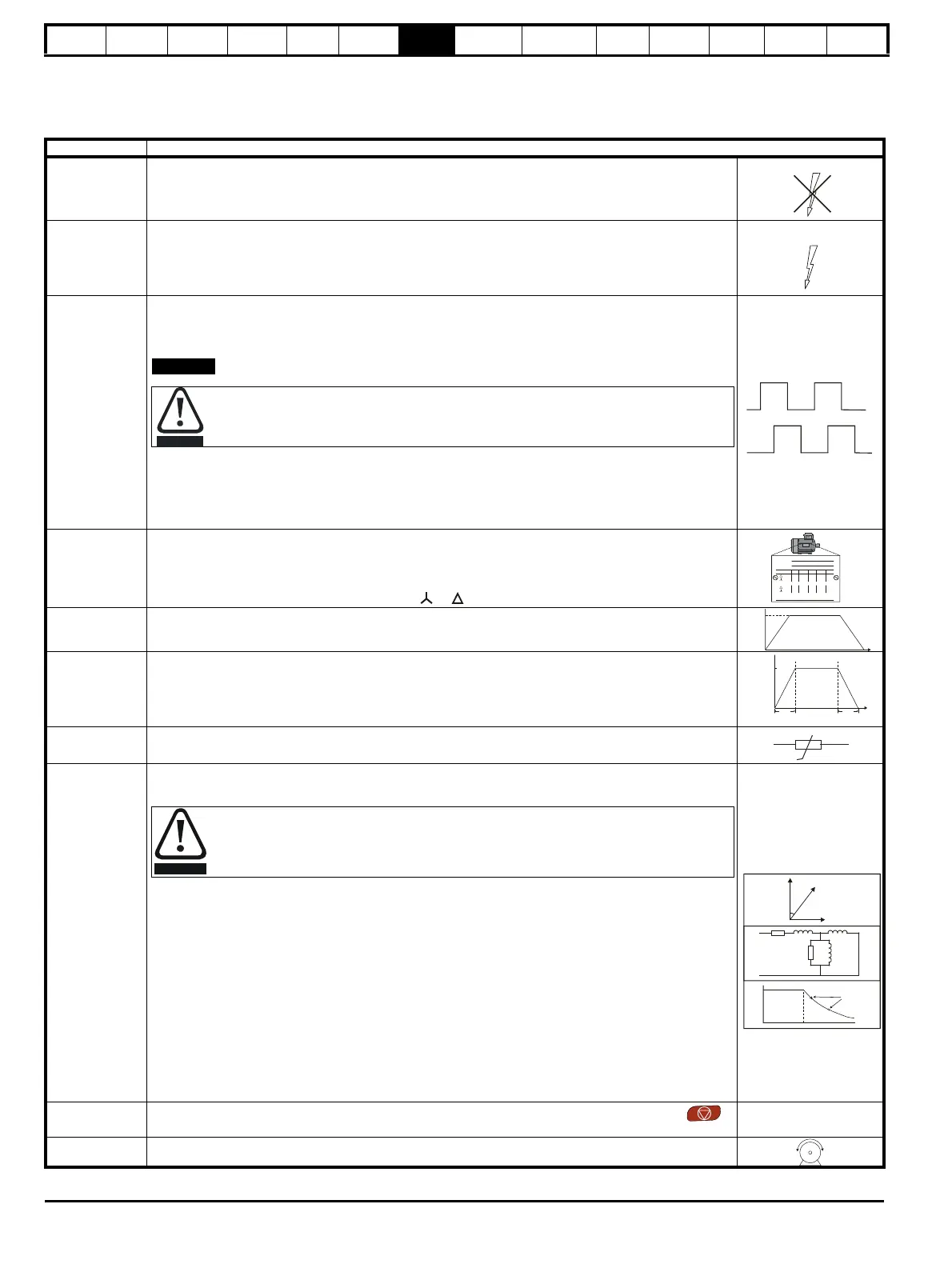
7.3.2 RFC - A mode (with position feedback)
Induction motor with position feedback
For simplicity only an incremental quadrature encoder will be considered here. For information on setting up one of the other supported speed
feedback devices, refer to section 7.4 Setting up a feedback device on page 111.
Action Detail
Before power-up
Ensure:
• The drive enable signal is not given (terminals 11 and 13)
• Run signal is not given
• Motor and feedback device are connected
Power-up the
drive
Verify that RFC-A mode is displayed as the drive powers up. If the mode is incorrect see section 5.6 Changing
the operating mode on page 93.
Ensure:
• Drive displays ‘Inhibit’
If the drive trips, see Chapter 13 Diagnostics on page 247.
Set motor
feedback
parameters
Incremental encoder basic set-up
Enter:
• Drive encoder type in Pr 03.038 = AB (0): Quadrature encoder
• Encoder power supply in Pr. 03.036 = 5 V (0), 8 V (1) or 15 V (2).
If output voltage from the encoder is >5 V, then the termination resistors must be disabled
Pr 03.039 to 0.
• Drive encoder Lines Per Revolution (LPR) in Pr 03.034 (set according to encoder)
• Drive encoder termination resistor setting in Pr 03.039:
0 = A-A\, B-B\, Z-Z\ termination resistors disabled
1 = A-A\, B-B\, termination resistors enabled, Z-Z\ termination resistors disabled
2 = A-A\, B-B\, Z-Z\ termination resistors enabled
Enter motor
nameplate
details
Enter:
• Motor rated frequency in Pr 00.047 (Hz)
• Motor rated current in Pr 00.046 (A)
• Motor rated speed in Pr 00.045 (rpm)
• Motor rated voltage in Pr 00.044 (V) - check if or connection
Set maximum
speed
Enter:
• Maximum speed in Pr 00.002 (rpm)
Set acceleration /
deceleration
rates
Enter:
• Acceleration rate in Pr 00.003 (s/1000 rpm)
• Deceleration rate in Pr 00.004 (s/1000 rpm) (If braking resistor installed, set Pr 00.015 = Fast. Also ensure
Pr 10.030, Pr 10.031 and Pr 10.061 are set correctly, otherwise premature ‘Brake R Too Hot’ trips may be
seen).
Motor thermistor
set-up
The motor thermistor connection is made through the drive encoder port (terminal 15). The thermistor type is
selected in P1 Thermistor Type (03.118).
Autotune
The drive is able to perform either a stationary or a rotating autotune. The motor must be at a standstill before
an autotune is enabled. A stationary autotune will give moderate performance whereas a rotating autotune will
give improved performance as it measures the actual values of the motor parameters required by the drive.
• A stationary autotune can be used when the motor is loaded and it is not possible to uncouple the load
from the motor shaft. The stationary autotune measures the stator resistance and transient inductance of
the motor. These are used to calculate the current loop gains, and at the end of the test the values in
Pr 00.038 and Pr 00.039 are updated. A stationary autotune does not measure the power factor of the
motor so the value on the motor nameplate must be entered into Pr 00.043.
• A rotating autotune should only be used if the motor is uncoupled. A rotating autotune first performs a
stationary autotune before rotating the motor at
2
/
3
base speed in the direction selected. The rotating
autotune measures the stator inductance of the motor and calculates the power factor.
To perform an autotune:
•Set Pr 00.040 = 1 for a stationary autotune or set Pr 00.040 = 2 for a rotating autotune
• Close the drive enable signal
(terminals 11 and 13). The drive will display ’Ready’.
• Close the run signal (terminal 7 or 8). The
upper row of the display will flash ’Auto Tune’ while the drive is
performing the autotune.
• Wait for the drive to display ’Ready’ or ‘Inhibit’ and for the motor to come to a standstill
If the drive trips, see Chapter 13 Diagnostics on page 247.
• Remove the drive enable and run signal from the drive.
Save parameters
Select 'Save Parameters' in Pr
mm.000
(alternatively enter a value of 1000 in Pr
mm.000
) and press red
reset button or toggle the reset digital input.
Run Drive is now ready to run
Setting the encoder voltage supply too high for the encoder could result in damage to the feedback
device.
Mot X XXXXXXXXX
No XXXXXXXXXX kg
IP55 I.cl F C 40 s S1
°
VHzmin
-1
kW cos
φ
A
230
400
50 1445 2.20 0.80 8.50
4.90
CN = 14.5Nm
240
415
50 1445 2.20 0.76 8.50
4.90
CN = 14.4Nm
CTP- VEN 1PHASE 1=0,46A P=110W R.F 32MN
I.E.C 34 1(87)
A rotating autotune will cause the motor to accelerate up to
2
/
3
base speed in the direction selected
regardless of the reference provided. Once complete the motor will coast to a stop. The enable signal
must be removed before the drive can be made to run at the required reference.
The drive can be stopped at any time by removing the run signal or removing the drive enable.

 Loading...


