Safety
information
Product
information
Mechanical
installation
Electrical
installation
Getting
started
Basic
parameters
Running
the motor
Optimization
NV Media Card
Operation
Onboard
PLC
Advanced
parameters
Technical
data
Diagnostics
UL listing
information
80 Unidrive M702 User Guide
Issue Number: 3
Refer to section 4.16 SAFE TORQUE OFF (STO) on page 86 for further
information.
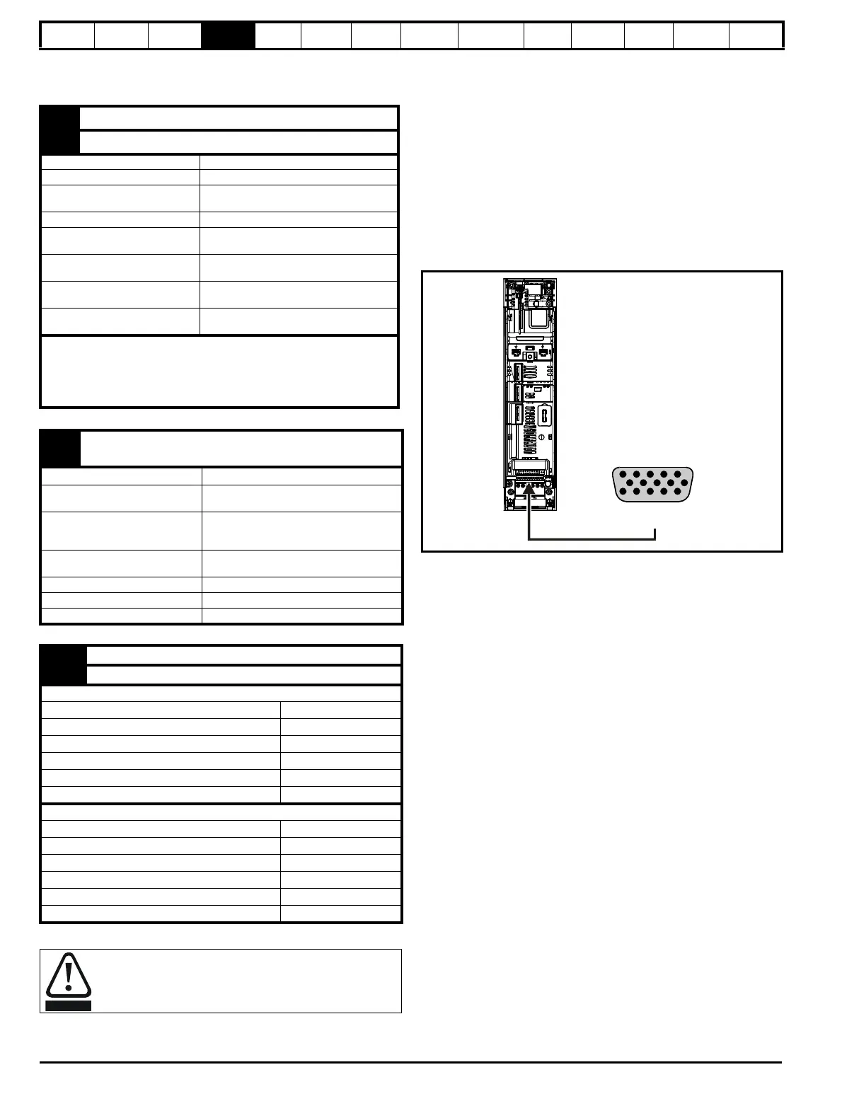
4.15 Position feedback connections
The following functions are provided via the 15-way high density D-type
connector on the drive:
• Two position feedback interfaces (P1 and P2).
• One encoder simulation output.
• Two freeze trigger inputs (marker inputs).
• One thermistor input.
The P1 position interface is always available but the availability of the P2
position interface and the encoder simulation output depends on the
position feedback device used on the P1 position interface, as shown in
Table 4-27.
4.15.1 Location of position feedback connector
Figure 4-45 Location of the position feedback
11 SAFE TORQUE OFF function input 1 (drive enable)
13
SAFE TORQUE OFF function input 2 (drive enable)
Type Positive logic only digital input
Voltage range 0 V to +24 V
Absolute maximum applied
voltage
30 V
Logic Threshold 10 V ± 5 V
Low state maximum voltage for
disable to SIL3 and PL e
5 V
Impedance
>4 mA @15 V from IEC 61131-2, type 1,
3.3
k Ω
Low state maximum current for
disable to SIL3 and PL e
0.5 mA
Response time
Nominal: 8 ms
Maximum: 20 ms
The SAFE TORQUE OFF function may be used in a safety-related application in
preventing the drive from generating torque in the motor to a high level of
integrity. The system designer is responsible for ensuring that the complete
system is safe and designed correctly according to the relevant safety
standards. If the SAFE TORQUE OFF function is not required, these terminals
are used for enabling the drive.
41
Relay contacts
42
Default function Drive OK indicator
Contact voltage rating
240 Vac, Installation over-voltage
category II
Contact maximum current rating
2 A AC 240 V
4 A DC 30 V resistive load
0.5 A DC 30 V inductive load (L/R = 40 ms)
Contact minimum recommended
rating
12 V 100 mA
Contact type Normally open
Default contact condition Closed when power applied and drive OK
Update period 4 ms
51 0 V
52 +24 Vdc
Size 6
Nominal operating voltage 24.0 Vdc
Minimum continuous operating voltage 18.6 Vdc
Maximum continuous operating voltage 28.0 Vdc
Minimum startup voltage 18.4 Vdc
Maximum power supply requirement 40 W
Recommended fuse 4 A @ 50 Vdc
Size 7 and 8
Nominal operating voltage 24.0 Vdc
Minimum continuous operating voltage 19.2 Vdc
Maximum continuous operating voltage 30 Vdc
Minimum startup voltage 21.6 Vdc
Maximum power supply requirement 60 W
Recommended fuse 3 A @ 50 Vdc
To prevent the risk of a fire hazard in the event of a fault, a
fuse or other over-current protection must be installed in the
relay circuit.

 Loading...


