Safety
information
Product
information
Mechanical
installation
Electrical
installation
Getting
started
Basic
parameters
Running
the motor
Optimization
NV Media Card
Operation
Onboard
PLC
Advanced
parameters
Technical
data
Diagnostics
UL listing
information
78 Unidrive M702 User Guide
Issue Number: 3
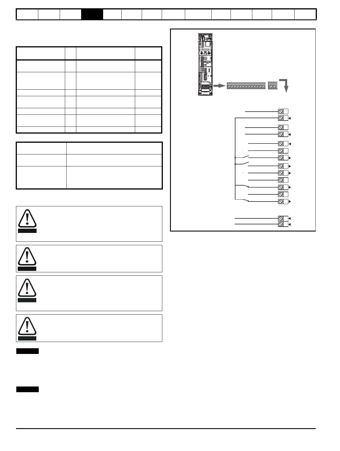
4.14 Control connections
4.14.1 General
Table 4-24 The control connections consist of:
Key:
All digital terminal functions (including the relay) can be programmed in
menu 8.
N
Any signal cables which are carried inside the motor cable (i.e. motor
thermistor, motor brake) will pick up large pulse currents via the cable
capacitance. The shield of these signal cables must be connected to
ground close to the point of exit of the motor cable, to avoid this noise
current spreading through the control system.
N
The SAFE TORQUE OFF drive enable terminal is a positive logic input
only. It is not affected by the setting of Input Logic Polarity (08.029).
Figure 4-44 Default terminal functions
*The SAFE TORQUE OFF / Drive enable terminal is a positive logic input
only.
Function Qty
Control parameters
available
Terminal
number
Digital input 2
Destination, invert, logic
select
7, 8
Digital input / output 2
Input / output mode select,
destination / source, invert,
logic select
4, 5
Relay 1 Source, invert 41, 42
Drive enable (SAFE
TORQUE OFF)
2 11, 13
+24 V User output 1 Source, invert 2
0 V common 5
1, 3, 6,
10, 12
+24 V External input 1 Destination, invert 9
Destination parameter:
Indicates the parameter which is being controlled
by the terminal / function
Source parameter:
Indicates the parameter being output by the
terminal
Mode parameter:
Digital - indicates the mode of operation of the
terminal, i.e. positive / negative logic (the Drive
Enable terminal is fixed in positive logic), open
collector.
The control circuits are isolated from the power circuits in the
drive by basic insulation (single insulation) only. The installer
must ensure that the external control circuits are insulated
from human contact by at least one layer of insulation
(supplementary insulation) rated for use at the AC supply
voltage.
If the control circuits are to be connected to other circuits
classified as Safety Extra Low Voltage (SELV) (e.g. to a
personal computer), an additional isolating barrier must be
included in order to maintain the SELV classification.
If any of the digital inputs (including the drive enable input)
are connected in parallel with an inductive load (i.e.
contactor or motor brake) then suitable suppression (i.e.
diode or varistor) should be used on the coil of the load. If no
suppression is used then over voltage spikes can cause
damage to the digital inputs and outputs on the drive.
Ensure the logic sense is correct for the control circuit to be
used. Incorrect logic sense could cause the motor to be
started unexpectedly.
Positive logic is the default state for the drive.
1
41
42
0 V common
0 V common
1
2
3
4
5
6
7
8
9
10
11
41
42
At zero speed
Run forward
Run reverse
SAFE TORQUE OFF
Input 1*
Relay
(Over voltage
category II)
Drive OK
13
+24 V
0 V common
0 V common
12
13
0 V common
+24 V
SAFE TORQUE OFF
Input 2*

 Loading...


