Safety
information
Product
information
Mechanical
installation
Electrical
installation
Getting
started
Basic
parameters
Running
the motor
Optimization
NV Media Card
Operation
Onboard
PLC
Advanced
parameters
Technical
data
Diagnostics
UL listing
information
254 Unidrive M702 User Guide
Issue Number: 3
EEPROM Fail Default parameters have been loaded
31
The EEPROM Fail trip indicates that default parameters have been loaded. The exact cause/reason of the trip can be
identified from the sub-trip number.
Recommended actions:
• Default the drive and perform a reset
• Allow sufficient time to perform a save before the supply to the drive is removed
• If the trip persists - return drive to supplier
Encoder 1 Drive position feedback interface power supply overload
189
The Encoder 1 trip indicates that the drive encoder power supply has been overloaded. Terminals 13 and 14 of the 15 way
D type connector can supply a maximum current of 200 mA @ 15 V or 300 mA @ 8 V and 5 V.
Recommended actions:
• Check encoder power supply wiring
• Disable the termination resistors (Pr 03.039 set to 0) to reduce current consumption
• For 5 V encoders with long cables, select 8 V (Pr 03.036) and fit a 5 V voltage regulator close to the encoder
• Check the encoder specification to confirm if it is compatible with the encoder port power supply current capability
• Replace the encoder
• Use an external power supply with higher current capability
Encoder 2 Drive encoder (Feedback) wire break
190
The Encoder 2 trip indicates that the drive has detected a wire break on the 15 way D-type connector on the drive. The
exact cause of the trip can be identified from the sub-trip number.
Recommended actions:
• If wire break detection on the drive encoder input is not required, set Pr 03.040 = XXX0 to disable the Encoder 2 trip
• Check cable continuity
• Check wiring of feedback signals is correct
• Check encoder power supply is set correctly (Pr 03.036)
• Replace encoder
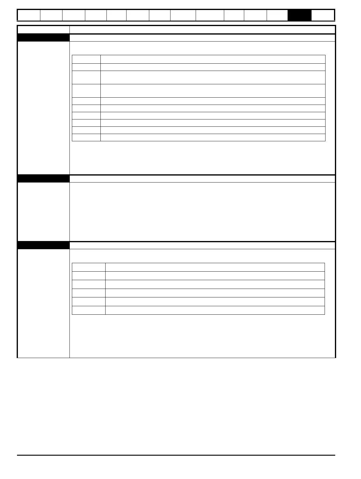
Trip Diagnosis
Sub-trip Reason
1 The most significant digit of the internal parameter database version number has changed
2
The CRC's applied to the parameter data stored in internal non-volatile memory indicate that a valid set
of parameters cannot be loaded
3
The drive mode restored from internal non-volatile memory is outside the allowed range for the product
or the derivative image does not allow the previous drive mode
4 The drive derivative image has changed
5 The power stage hardware has changed
6 The internal I/O hardware has changed
7 The position feedback interface hardware has changed
8 The control board hardware has changed
9 The checksum on the non-parameter area of the EEPROM has failed
Sub-trip Reason
10 Drive position feedback interface 1 on any input
20 Drive position feedback interface 2 on any input
11 Drive position feedback interface 1 on the A channel
12 Drive position feedback interface 1 on the B channel
13 Drive position feedback interface 1 on the Z channel

 Loading...


