Safety
information
Product
information
Mechanical
installation
Electrical
installation
Getting
started
Basic
parameters
Running
the motor
Optimization
NV Media Card
Operation
Onboard
PLC
Advanced
parameters
Technical
data
Diagnostics
UL listing
information
56 Unidrive M702 User Guide
Issue Number: 3
4.2.2 Supplies requiring line reactors
Input line reactors reduce the risk of damage to the drive resulting from
poor phase balance or severe disturbances on the supply network.
Where line reactors are to be used, reactance values of approximately 2
% are recommended. Higher values may be used if necessary, but may
result in a loss of drive output (reduced torque at high speed) because of
the voltage drop.
For all drive ratings, 2 % line reactors permit drives to be used with a
supply unbalance of up to 3.5 % negative phase sequence (equivalent to
5% voltage imbalance between phases).
Severe disturbances may be caused by the following factors, for example:
• Power factor correction equipment connected close to the drive.
• Large DC drives having no or inadequate line reactors connected to
the supply.
• Across the line (DOL) started motor(s) connected to the supply such
that when any of these motors are started, the voltage dip exceeds
20 %.
Such disturbances may cause excessive peak currents to flow in the
input power circuit of the drive. This may cause nuisance tripping, or in
extreme cases, failure of the drive.
Drives of low power rating may also be susceptible to disturbance when
connected to supplies with a high rated capacity.
Line reactors are particularly recommended for use with the following
drive models when one of the above factors exists, or when the supply
capacity exceeds 175 kVA:
03200050, 03200066, 03200080, 03200106,
03400025, 03400031, 03400045, 03400062
Model sizes 03400078 to 07600540 have an internal DC choke and
082001160 to 08600860 have internal AC line chokes so they do not
require AC line reactors except for cases of excessive phase unbalance
or extreme supply conditions.
When required, each drive must have its own reactor(s). Three individual
reactors or a single three-phase reactor should be used.
Reactor current ratings
The current rating of the line reactors should be as follows:
Continuous current rating:
Not less than the continuous input current rating of the drive
Repetitive peak current rating:
Not less than twice the continuous input current rating of the drive
4.2.3 Input inductor calculation
To calculate the inductance required (at Y%), use the following equation:
Where:
I = drive rated input current (A)
L = inductance (H)
f = supply frequency (Hz)
V = voltage between lines
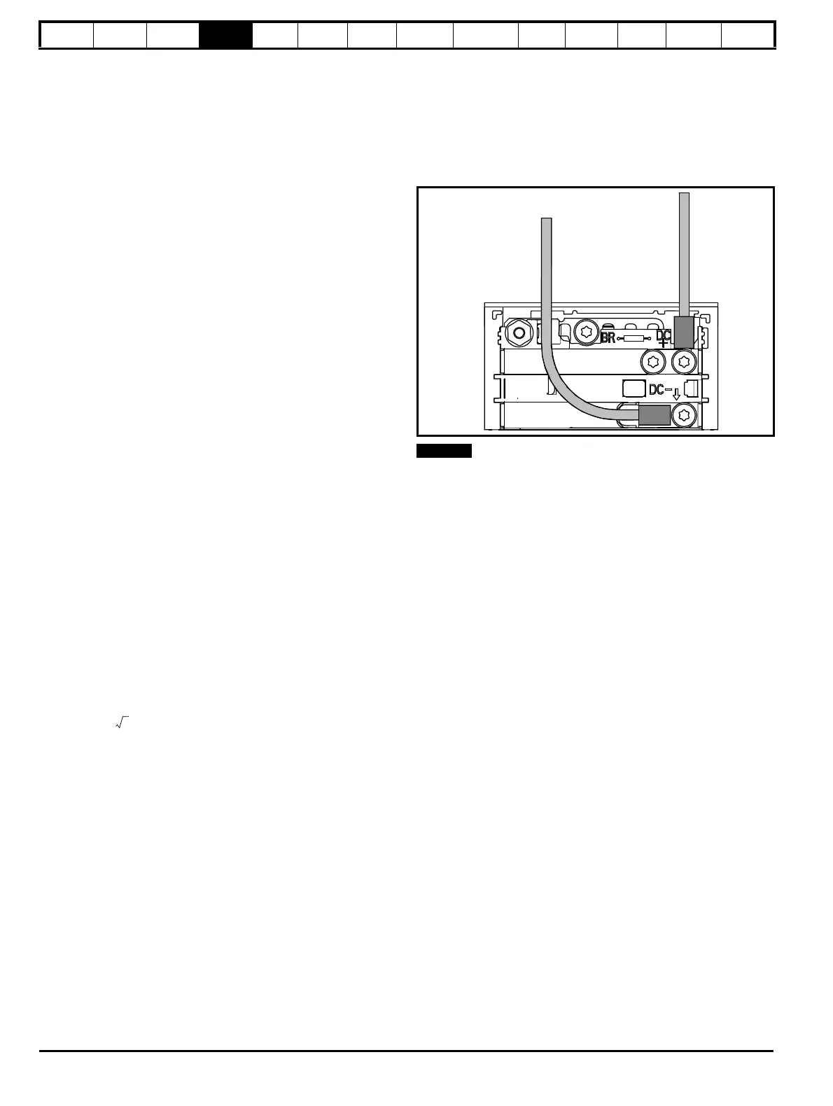
4.3 Supplying the drive with DC
All drive sizes have the option to be powered from an external DC power
supply. Refer to section 3.12 Electrical terminals on page 47 to identify
the location of DC supply connections.
The DC supply connections for size 3 are located under the DC / Braking
terminal cover. Figure 4-10 shows DC supply connections and cable
routing.
Figure 4-10 DC supply connections (size 3 shown)
The Internal EMC filter and plastics have been removed from the above
Figure 4-10 to demonstrate the routing of the DC cables.
L
Y
100
----------
V
3
-------
×
1
2πfI
------------
×=

 Loading...


