Safety
information
Product
information
Mechanical
installation
Electrical
installation
Getting
started
Basic
parameters
Running
the motor
Optimization
NV Media Card
Operation
Onboard
PLC
Advanced
parameters
Technical
data
Diagnostics
UL listing
information
Unidrive M702 User Guide 265
Issue Number: 3
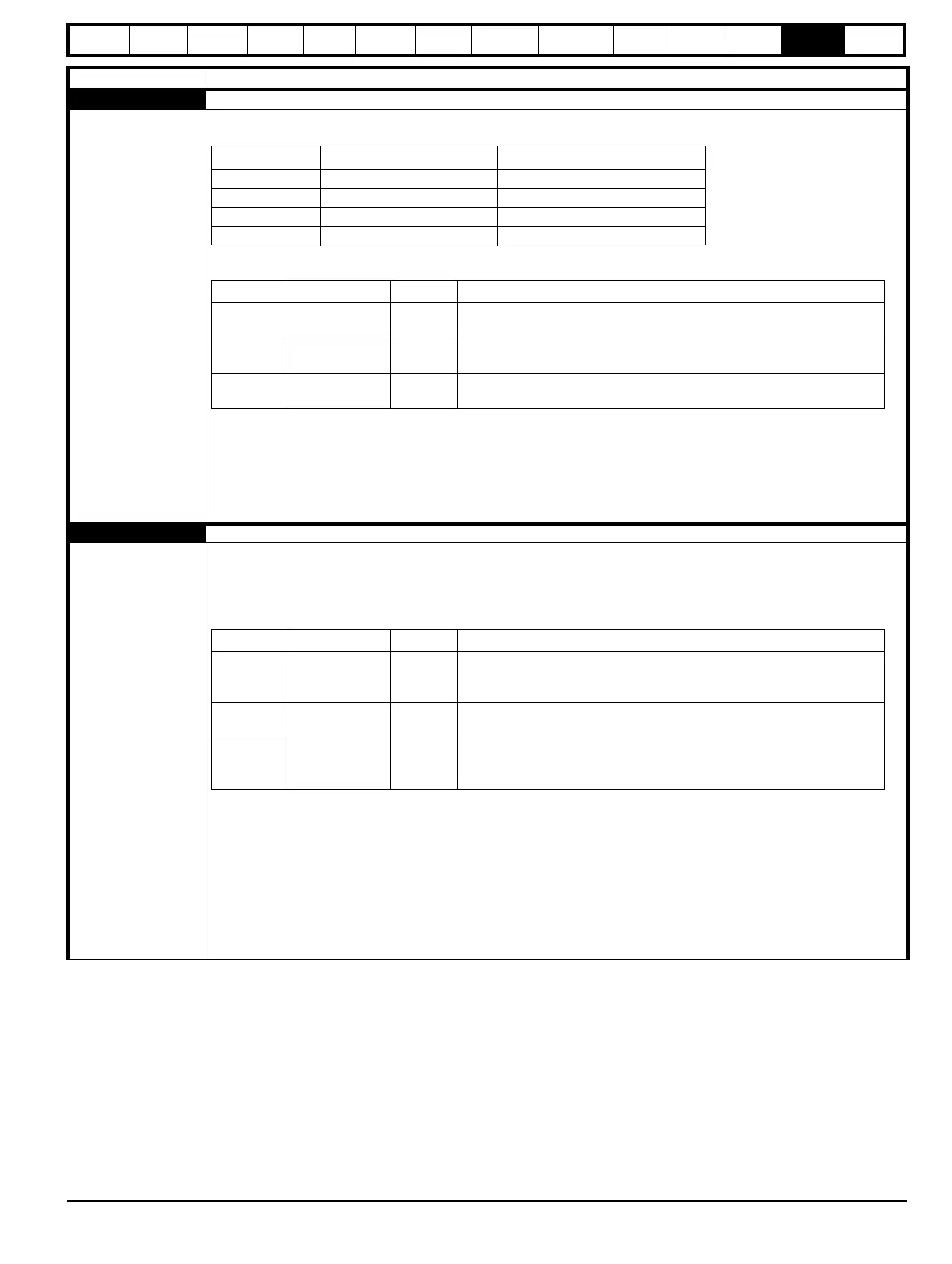
Over Volts DC bus voltage has exceeded the peak level or maximum continuous level for 15 seconds
2
The Over Volts trip indicates that the DC bus voltage has exceeded the VM_DC_VOLTAGE[MAX] or
VM_DC_VOLTAGE_SET[MAX] for 15 s. The trip threshold varies depending on voltage rating of the drive as shown below.
Sub-trip Identification
Recommended actions:
• Increase deceleration ramp (Pr 00.004)
• Decrease the braking resistor value (staying above the minimum value)
• Check nominal AC supply level
• Check for supply disturbances which could cause the DC bus to rise
• Check motor insulation using a insulation tester
Phase Loss Supply phase loss
32
The Phase Loss trip indicates that the drive has detected an input phase loss or large supply imbalance. The drive will
attempt to stop the motor before this trip is initiated. If the motor cannot be stopped in 10 seconds the trip occurs
immediately. The Phase Loss trip works by monitoring the ripple voltage on the DC bus of the drive, if the DC bus ripple
exceeds the threshold, the drive will trip on Phase Loss. Potential causes of the DC bus ripple are input phase loss, Large
supply impedance and severe output current instability.
Input phase loss detection can be disabled when the drive is required to operate from the DC supply or from a single phase
supply in Input Phase Loss Detection Mode (06.047).
Recommended actions:
• Check the AC supply voltage balance and level at full load
• Check the DC bus ripple level with an isolated oscilloscope
• Check the output current stability
• Reduce the duty cycle
• Reduce the motor load
• Disable the phase loss detection, set Pr 06.047 to 2.
Trip Diagnosis
Voltage rating VM_DC_VOLTAGE[MAX] VM_DC_VOLTAGE_SET[MAX]
200 415 410
400 830 815
575 990 970
690 1190 1175
Source xx y zz
Control
system
00 0
01: Instantaneous trip when the DC bus voltage exceeds
VM_DC_VOLTAGE[MAX].
Control
system
00 0
02: Time delayed trip indicating that the DC bus voltage is above
VM_DC_VOLTAGE_SET[MAX].
Power
system
Power module
number
0
00: Instantaneous trip when the DC bus voltage exceeds
VM_DC_VOLTAGE[MAX].
Source xx y zz
Control
system
00 0
00: Phase loss detected based on control system feedback. The drive
attempts to stop the drive before tripping unless bit 2 of Action On Trip
Detection (10.037) is set to one.
Power
system
Power module
number
Rectifier
number
00: Phase loss has been detected by the rectifier module
Control
system
01: Mains loss has been detected by the rectifier module in a multi-power
module system, where this must be treated as a phase loss condition to
prevent damage to the drive.

 Loading...


