Safety
information
Product
information
Mechanical
installation
Electrical
installation
Getting
started
Basic
parameters
Running
the motor
Optimization
NV Media Card
Operation
Onboard
PLC
Advanced
parameters
Technical
data
Diagnostics
UL listing
information
64 Unidrive M702 User Guide
Issue Number: 3
Table 4-15 Maximum motor cable lengths (575 V drives)
Table 4-16 Maximum motor cable lengths (690 V drives)
4.9.2 High-capacitance / reduced diameter cables
The maximum cable length is reduced from that shown in Section
4.9.1 Cable types and lengths if high capacitance or reduced diameter
motor cables are used.
Most cables have an insulating jacket between the cores and the armor
or shield; these cables have a low capacitance and are recommended.
Cables that do not have an insulating jacket tend to have high
capacitance; if a cable of this type is used, the maximum cable length is
half that quoted in the tables, (Figure 4-15 shows how to identify the two
types).
Figure 4-15 Cable construction influencing the capacitance
The maximum motor cable lengths specified in Section 4.9.1 Cable
types and lengths is shielded and contains four cores. Typical
capacitance for this type of cable is 130 pF/m (i.e. from one core to all
others and the shield connected together).
4.9.3 Motor winding voltage
The PWM output voltage can adversely affect the inter-turn insulation in
the motor. This is because of the high rate of change of voltage, in
conjunction with the impedance of the motor cable and the distributed
nature of the motor winding.
For normal operation with AC supplies up to 500 Vac and a standard
motor with a good quality insulation system, there is no need for any
special precautions. In case of doubt the motor supplier should be
consulted. Special precautions are recommended under the following
conditions, but only if the motor cable length exceeds 10 m:
• AC supply voltage exceeds 500 V
• DC supply voltage exceeds 670 V
• Operation of 400 V drive with continuous or very frequent sustained
braking
• Multiple motors connected to a single drive
For multiple motors, the precautions given in section 4.9.4 Multiple
motors on page 64 should be followed.
For the other cases listed, it is recommended that an inverter-rated
motor be used taking into account the voltage rating of the inverter. This
has a reinforced insulation system intended by the manufacturer for
repetitive fast-rising pulsed voltage operation.
Users of 575 V NEMA rated motors should note that the specification for
inverter-rated motors given in NEMA MG1 section 31 is sufficient for
motoring operation but not where the motor spends significant periods
braking. In that case an insulation peak voltage rating of 2.2 kV is
recommended.
If it is not practical to use an inverter-rated motor, an output choke
(inductor) should be used. The recommended type is a simple iron-cored
component with a reactance of about 2 %. The exact value is not critical.
This operates in conjunction with the capacitance of the motor cable to
increase the rise-time of the motor terminal voltage and prevent
excessive electrical stress.
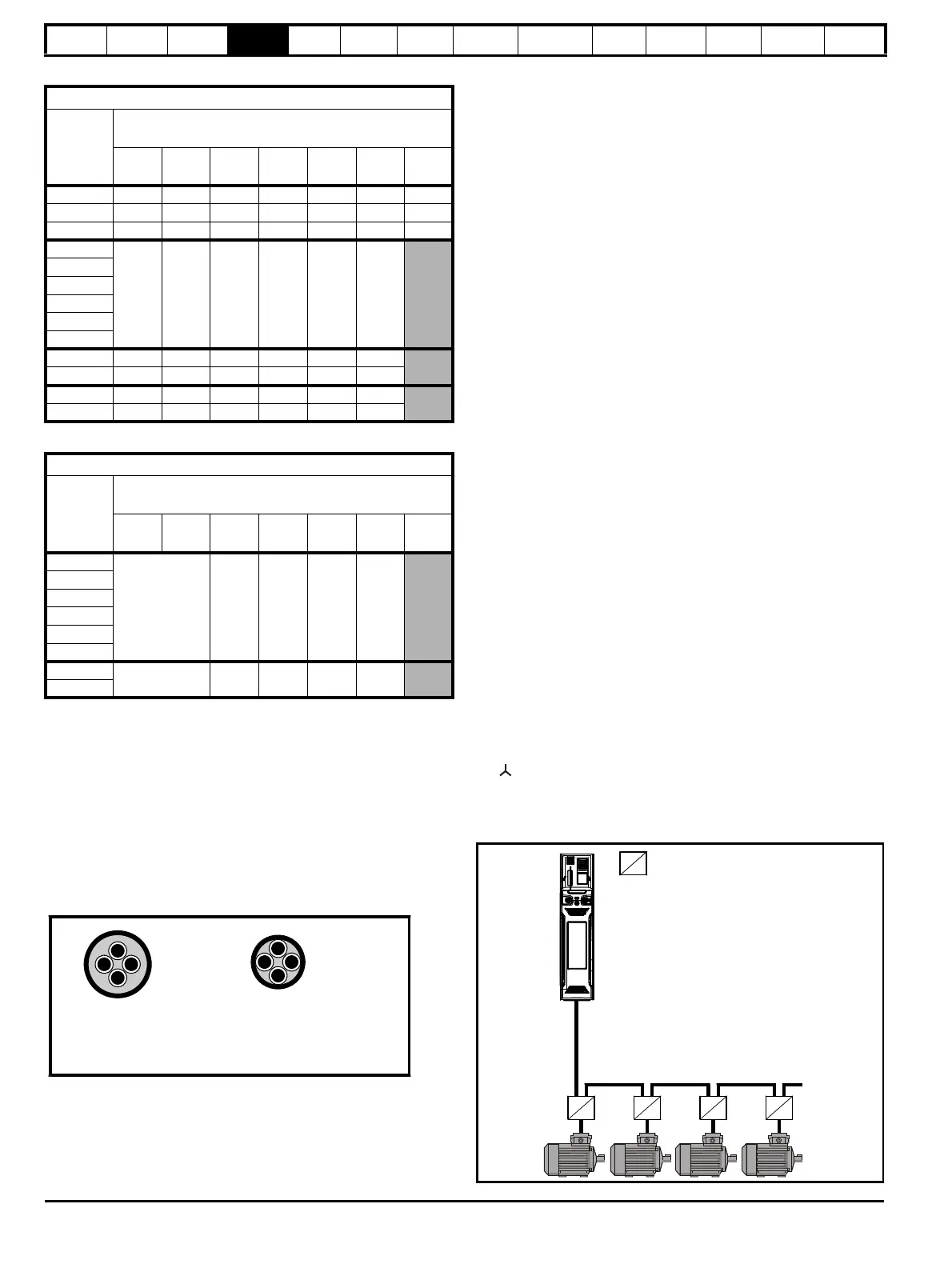
4.9.4 Multiple motors
Open-loop only
If the drive is to control more than one motor, one of the fixed V/F modes
should be selected (Pr 05.014 = Fixed or Squared). Make the motor
connections as shown in Figure 4-16 and Figure 4-17. The maximum
motor cable lengths specified in section 4.9.1 Cable types and lengths
on page 63 apply to the sum of the total cable lengths from the drive to
each motor. It is recommended that each motor is connected through a
protection relay since the drive cannot protect each motor individually
For connection, a sinusoidal filter or an output inductor must be
connected as shown in Figure 4-17, even when the cable lengths are
less than the maximum permissible. For details of inductor sizes, refer to
the supplier of the drive.
Figure 4-16 Preferred chain connection for multiple motors
575 V Nominal AC supply voltage
Model
Maximum permissible motor cable length for each of
the following switching frequencies
2
kHz
3
kHz
4
kHz
6
kHz
8
kHz
12
kHz
16
kHz
05500030
05500040
05500069
06500100
300 m
(984 ft)
200 m
(660 ft)
150 m
(490 ft)
100 m
(330 ft)
75 m
(245 ft)
50 m
(165 ft)
06500150
06500190
06500230
06500290
06500350
07500440
07500550
08500630
08500860
690 V Nominal AC supply voltage
Model
Maximum permissible motor cable length for each of
the following switching frequencies
2
kHz
3
kHz
4
kHz
6
kHz
8
kHz
12
kHz
16
kHz
07600190
250 m
(820 ft)
185 m
(607 ft)
125 m
(410 ft)
90 m
(295 ft)
07600240
07600290
07600380
07600440
07600540
08600630
250 m
(820 ft)
185 m
(607 ft)
125 m
(410 ft)
90 m
(295 ft)
08600860
Normal capacitance
Shield or armour
separated from the cores
High capacitance
Shield or armour close
to the cores
Motor protection
relay
Chain connection (preferred)

 Loading...


