Safety
information
Product
information
Mechanical
installation
Electrical
installation
Getting
started
Basic
parameters
Running
the motor
Optimization
NV Media Card
Operation
Onboard
PLC
Advanced
parameters
Technical
data
Diagnostics
UL listing
information
Unidrive M702 User Guide 57
Issue Number: 3
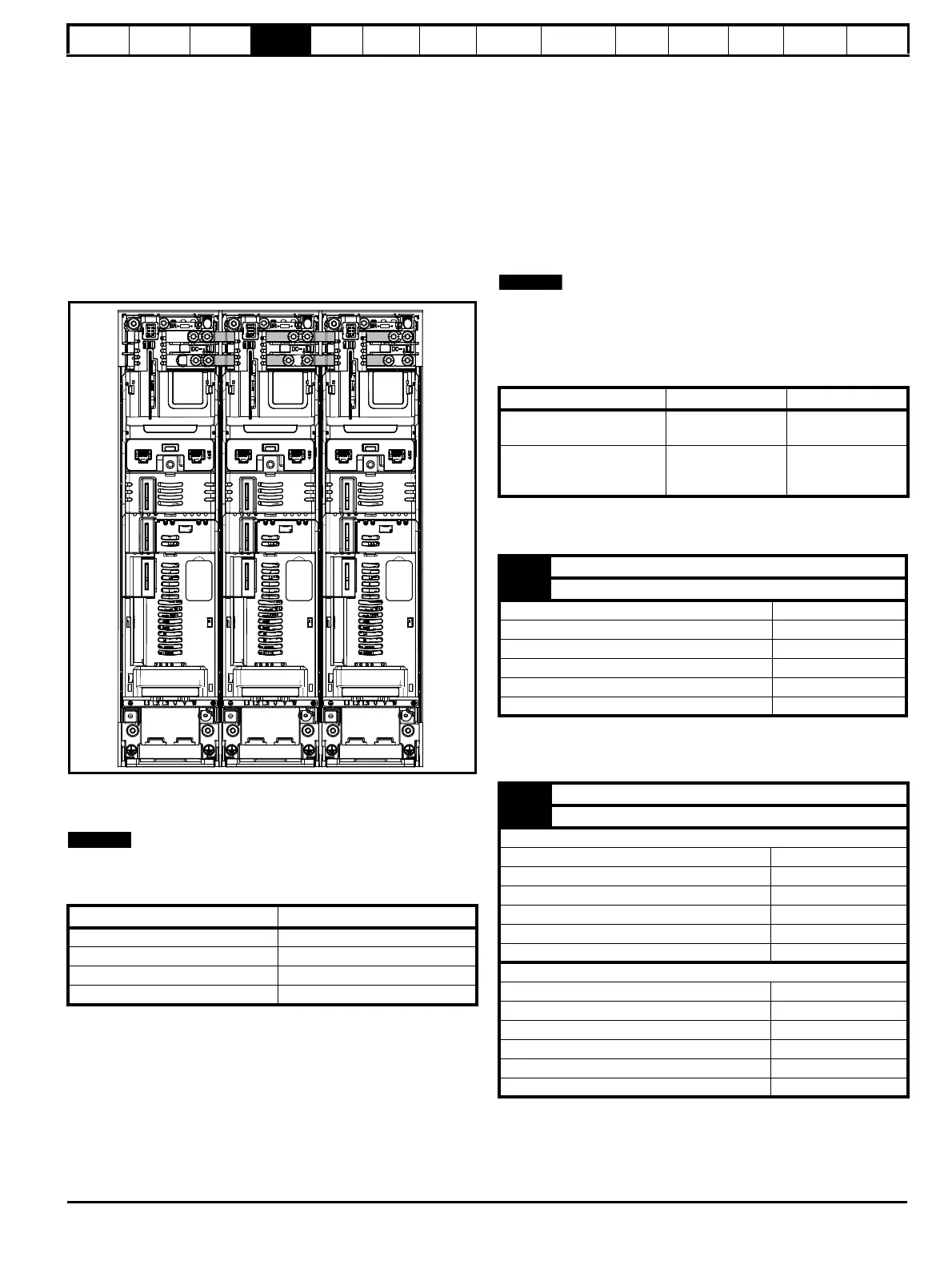
4.4 DC bus paralleling
DC bus paralleling using standard cable / busbars is supported by all
frame sizes.
On frame sizes 3, 4, 5 and 6 terminal and enclosure design enables the
DC bus of a number of drives to be connected together using pre-made
busbars. The diagram below shows how the busbar links connect the
DC bus of several drives together.
The connecting of the DC bus between several drives is typically used to:
1. Return energy from a drive which is being overhauled by the load to
a second motoring drive.
2. Allow the use of one braking resistor to dissipate regenerative
energy from several drives.
Figure 4-11 DC bus paralleling (size 3 shown)
There are limitations to the combinations of drives which can be used in
this configuration.
For application data, contact the supplier of the drive.
The DC bus paralleling kit is not supplied with the drive but available to
order from Control Techniques.
Table 4-2 DC bus paralleling kit part numbers
4.5 24 Vdc supply
The 24 Vdc supply connected to control terminals 1 & 2 provides the
following functions:
• It can be used to supplement the drive's own internal 24 V supply
when multiple option modules are being used and the current drawn
by these module is greater than the drive can supply.
• It can be used as a back-up power supply to keep the control circuits
of the drive powered up when the line power supply is removed. This
allows any fieldbus modules, application modules, encoders or serial
communications to continue to operate.
• It can be used to commission the drive when the line power supply is
not available, as the display operates correctly. However, the drive
will be in the Under voltage trip state unless either line power supply
or low voltage DC operation is enabled, therefore diagnostics may
not be possible. (Power down save parameters are not saved when
using the 24 V back-up power supply input).
• If the DC bus voltage is too low to run the main SMPS in the drive,
then the 24 V supply can be used to supply all the low voltage power
requirements of the drive. Low Under Voltage Threshold Select
(06.067) must also be enabled for this to happen.
On size 6 and larger, if the power 24 Vdc supply is not connected none
of the above mentioned functions can be used and “Waiting For Power
Systems” will be displayed on the keypad. The location of the power 24
Vdc can be identified from Figure 4-12.
Table 4-3 24 Vdc Supply connections
The working voltage range of the control 24 V power supply is as
follows:
Minimum and maximum voltage values include ripple and noise. Ripple
and noise values must not exceed 5 %.
The working range of the 24 V power supply is as follows:
Size CT part number
3 3470-0048-00
4 3470-0061-00
5 3470-0068-00
6 3470-0063-00
Function Sizes 3-5 Sizes 6-8
Supplement the drive’s
internal supply
Terminal
1, 2
Terminal
1, 2
Back-up supply for the
control circuit
Terminal
1, 2
Terminal
1, 2
51, 52
1 +24 Vdc
2 0 V
Nominal operating voltage 24.0 Vdc
Minimum continuous operating voltage 19.2 V
Maximum continuous operating voltage 28.0 V
Minimum start up voltage 21.6 V
Maximum power supply requirement at 24 V 40 W
Recommended fuse 3 A, 50 Vdc
51 0 V
52 +24 Vdc
Size 6
Nominal operating voltage 24.0 Vdc
Minimum continuous operating voltage 18.6 Vdc
Maximum continuous operating voltage 28.0 Vdc
Minimum startup voltage 18.4 Vdc
Maximum power supply requirement 40 W
Recommended fuse 4 A @ 50 Vdc
Size 7 and 8
Nominal operating voltage 24.0 Vdc
Minimum continuous operating voltage 19.2 Vdc
Maximum continuous operating voltage 30 Vdc
Minimum startup voltage 21.6 Vdc
Maximum power supply requirement 60 W
Recommended fuse 3 A @ 50 Vdc

 Loading...


