Safety
information
Product
information
Mechanical
installation
Electrical
installation
Getting
started
Basic
parameters
Running
the motor
Optimization
NV Media Card
Operation
Onboard
PLC
Advanced
parameters
Technical
data
Diagnostics
UL listing
information
Unidrive M702 User Guide 39
Issue Number: 3
3.6.3 Enclosure sizing
1. Add the dissipation figures from section 12.1.2 Power dissipation on
page 232 for each drive that is to be installed in the enclosure.
2. If an external EMC filter is to be used with each drive, add the
dissipation figures from section 12.2.1 EMC filter ratings on
page 245 for each external EMC filter that is to be installed in the
enclosure.
3. If the braking resistor is to be mounted inside the enclosure, add the
average power figures from for each braking resistor that is to be
installed in the enclosure.
4. Calculate the total heat dissipation (in Watts) of any other equipment
to be installed in the enclosure.
5. Add the heat dissipation figures obtained above. This gives a figure
in Watts for the total heat that will be dissipated inside the enclosure.
Calculating the size of a sealed enclosure
The enclosure transfers internally generated heat into the surrounding
air by natural convection (or external forced air flow); the greater the
surface area of the enclosure walls, the better is the dissipation
capability. Only the surfaces of the enclosure that are unobstructed (not
in contact with a wall or floor) can dissipate heat.
Calculate the minimum required unobstructed surface area A
e
for the
enclosure from:
Where:
A
e
Unobstructed surface area in m
2
(1 m
2
= 10.9 ft
2
)
T
ext
Maximum expected temperature in
o
C outside the
enclosure
T
int
Maximum permissible temperature in
o
C inside the
enclosure
P Power in Watts dissipated by all heat sources in the
enclosure
k Heat transmission coefficient of the enclosure material
in W/m
2
/
o
C
Example
To calculate the size of an enclosure for the following:
• Two drives operating at the Normal Duty rating
• External EMC filter for each drive
• Braking resistors are to be mounted outside the enclosure
• Maximum ambient temperature inside the enclosure: 40°C
• Maximum ambient temperature outside the enclosure: 30°C
For example, if the power dissipation from each drive is 187 W and the
power dissipation from each external EMC filter is 9.2 W.
Total dissipation: 2 x (187 + 9.2) =392.4 W
Power dissipation for the drives and the external EMC filters can be
obtained from Chapter 12 Technical data on page 227
The enclosure is to be made from painted 2 mm (0.079 in) sheet steel
having a heat transmission coefficient of 5.5 W/m
2
/
o
C. Only the top,
front, and two sides of the enclosure are free to dissipate heat.
The value of 5.5 W/m
2
/ºC can generally be used with a sheet steel
enclosure (exact values can be obtained by the supplier of the material).
If in any doubt, allow for a greater margin in the temperature rise.
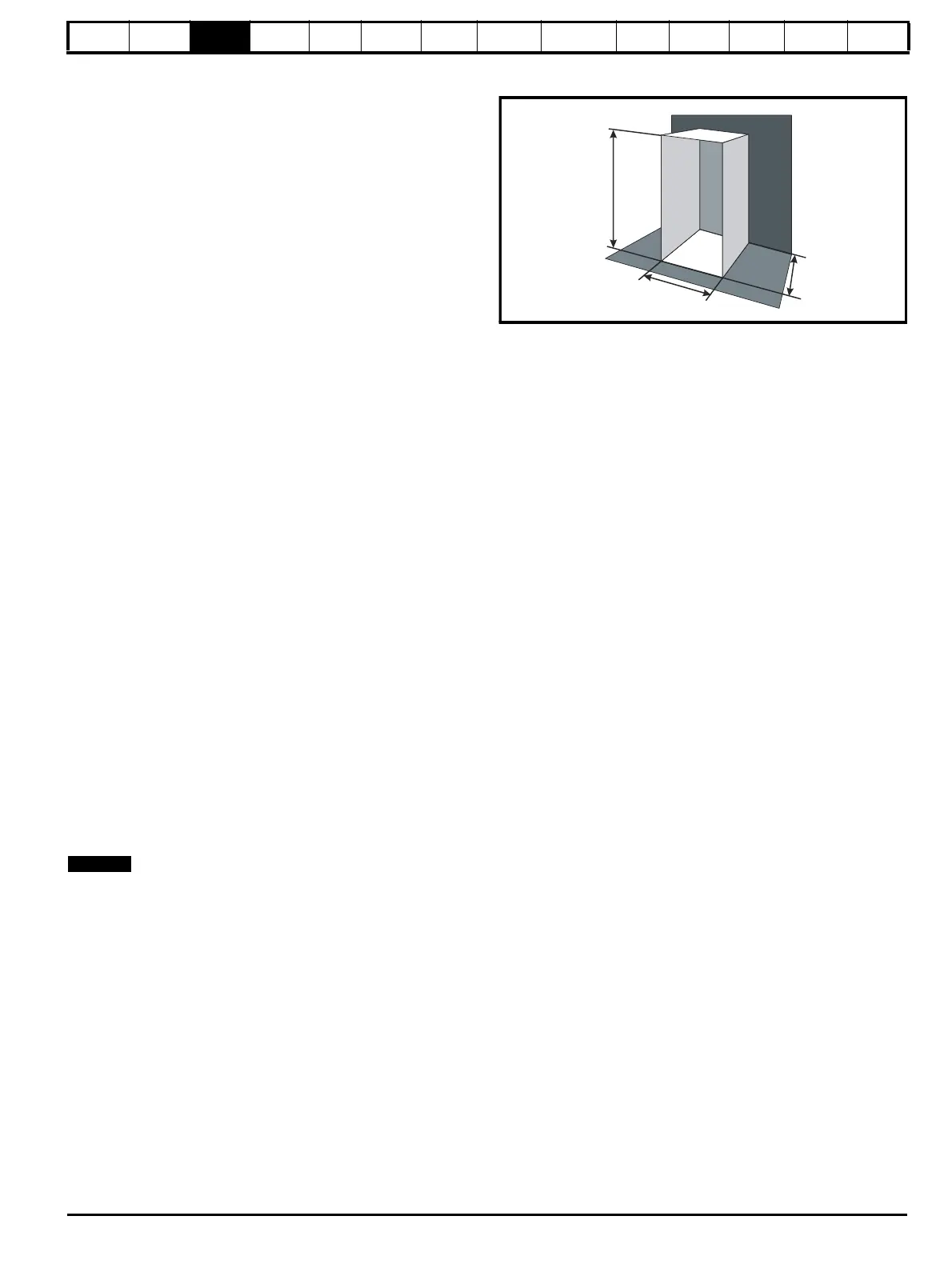
Figure 3-29 Enclosure having front, sides and top panels free to
dissipate heat
Insert the following values:
T
int
40 °C
T
ext
30 °C
k 5.5
P 392.4 W
The minimum required heat conducting area is then:
= 7.135 m
2
(77.8 ft
2
) (1 m
2
= 10.9 ft
2
)
Estimate two of the enclosure dimensions - the height (H) and depth (D),
for instance. Calculate the width (W) from:
Inserting H = 2m and D = 0.6 m, obtain the minimum width:
=1.821 m (71.7 in)
If the enclosure is too large for the space available, it can be made
smaller only by attending to one or all of the following:
• Using a lower PWM switching frequency to reduce the dissipation in
the drives
• Reducing the ambient temperature outside the enclosure, and/or
applying forced-air cooling to the outside of the enclosure
• Reducing the number of drives in the enclosure
• Removing other heat-generating equipment
Calculating the air-flow in a ventilated enclosure
The dimensions of the enclosure are required only for accommodating
the equipment. The equipment is cooled by the forced air flow.
Calculate the minimum required volume of ventilating air from:
Where:
V Air-flow in m
3
per hour (1 m
3
/hr = 0.59 ft
3
/min)
T
ext
Maximum expected temperature in
°C outside the
enclosure
T
int
Maximum permissible temperature in °C inside the
enclosure
P Power in Watts dissipated by all heat sources in the
enclosure
k Ratio of
Where:
P
0
is the air pressure at sea level
P
I
is the air pressure at the installation
Typically use a factor of 1.2 to 1.3, to allow also for pressure-drops in
dirty air-filters.
A
e
P
kT
int
T
ext
–()
-----------------------------------
=
A
e
392.4
5.5 40 30–()
---------------------------------
=
W
A
e
2HD–
HD+
--------------------------
=
W
7.135 2 2× 0.6×()–
20.6+
-----------------------------------------------------
=
V
3kP
T
int
T
ext
–
---------------------------
=

 Loading...


