Safety
information
Product
information
Mechanical
installation
Electrical
installation
Getting
started
Basic
parameters
Running
the motor
Optimization
NV Media Card
Operation
Onboard
PLC
Advanced
parameters
Technical
data
Diagnostics
UL listing
information
114 Unidrive M702 User Guide
Issue Number: 3
7.4.3 P2 position interface
This section shows the parameter settings which must be made to use each of the compatible feedback device types with the P2 position interface on
the drive. For more information on the parameters listed here please refer to the Parameter Reference Guide. If the position feedback device
connected to the P2 position interface is required to be used for motor control feedback then Pr 03.026 will need to be set to P2 Drive (1).
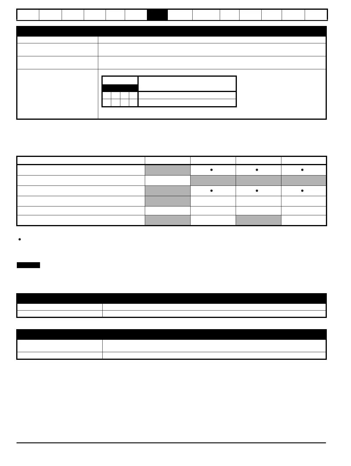
Table 7-4 Parameters required for feedback device set-up on the P2 position interface
Information required to be entered by the user.
Parameter can be set-up automatically by the drive through auto-configuration. Parameter must be set by the user if auto-configuration is
disabled (i.e. Pr 03.041 = Disabled (0)).
The P2 position interface does not have its own independent power supply output. Therefore, any position feedback device connected to the P2
position interface must either share the P1 power supply output on pin 13 of the 15-way D-type, or be supplied from an external source.
The termination resistors are always enabled on the P2 position interface. Wire break detection is not available when using AB, FD or FR position
feedback device types on the P2 position interface.
Table 7-4 shows a summary of the parameters required to set-up each feedback device. More detailed information follows.
Resolver
Device Type (03.038) Resolver (14)
Resolver Poles (03.065)
Set number of Resolver poles
2 poles, 4 poles, 6 poles, 8 poles
Resolver Excitation (03.066)
Set Resolver excitation voltage and frequency
6 V Auto (0), 4 V Auto (1), 6 V 6 kHz (2), 4 V 6 kHz (3), 6 V 8 kHz (4), 4 V 8 kHz (5)
Error Detection Level (03.040)
So for example, to enable the wire break error detection, set Pr 03.040 to 0001.
Bit
Description
3 2 1 0
xxx1
Enable wire break detection
1xxx
Disable trips Encoder 1 to Encoder 7
Parameter AB, FD, FR EnDat SSI BiSS
P2 Rotary Turns Bits (03.133)
P2 Rotary Lines Per Revolution (03.134)
P2 Comms Bits (03.135)
P2 Comms Baud Rate (03.137)
P2 Device Type (03.138)
P2 Auto–configuration Select (03.141)
Standard quadrature encoder (A, B, Z)
Device Type (03.138) AB (1) for a quadrature encoder
Rotary Line Per Revolution (03.134) Set to the number of lines per revolution of the encoder
Incremental encoder with Frequency and Direction (F and D), or Forward and Reverse (CW and CCW) signals
Device Type (03.138)
FD (2) for frequency and direction signals without commutation signals
FR (3) for forward and reverse signals without commutation signals
Rotary Line Per Revolution (03.134) Set to the number of pulses per revolution of the encoder divided by 2

 Loading...


