Safety
information
Product
information
Mechanical
installation
Electrical
installation
Getting
started
Basic
parameters
Running
the motor
Optimization
NV Media Card
Operation
Onboard
PLC
Advanced
parameters
Technical
data
Diagnostics
UL listing
information
54 Unidrive M702 User Guide
Issue Number: 3
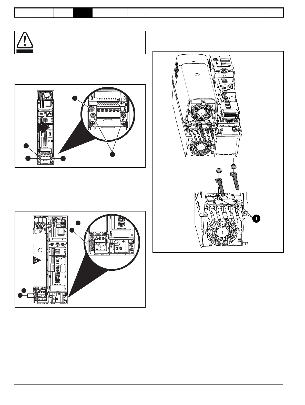
4.1.2 Ground connections
Size 3 and 4
On sizes 3 and 4, the supply and motor ground connections are made
using the M4 studs located either side of the drive near the plug-in power
connector. Refer to Figure 4-6 for additional ground connection.
Figure 4-6 Size 3 and 4 ground connections
1. Ground connection studs.
2. Additional ground connection.
Size 5
On size 5, the supply and motor ground connections are made using the
M5 studs located near the plug-in power connector. Refer to Figure 4-7
for additional ground connection.
Figure 4-7 Size 5 ground connections
1. Ground connection studs.
2. Additional ground connection.
Size 6
On a size 6, the supply and motor ground connections are made using
the M6 studs located above the supply and motor terminals. Refer to
Figure 4-8 below.
Figure 4-8 Size 6 ground connections
1. Ground connection studs
Electrochemical corrosion of grounding terminals
Ensure that grounding terminals are protected against
corrosion i.e. as could be caused by condensation.

 Loading...


