Safety
information
Product
information
Mechanical
installation
Electrical
installation
Getting
started
Basic
parameters
Running
the motor
Optimization
NV Media Card
Operation
Onboard
PLC
Advanced
parameters
Technical
data
Diagnostics
UL listing
information
82 Unidrive M702 User Guide
Issue Number: 3
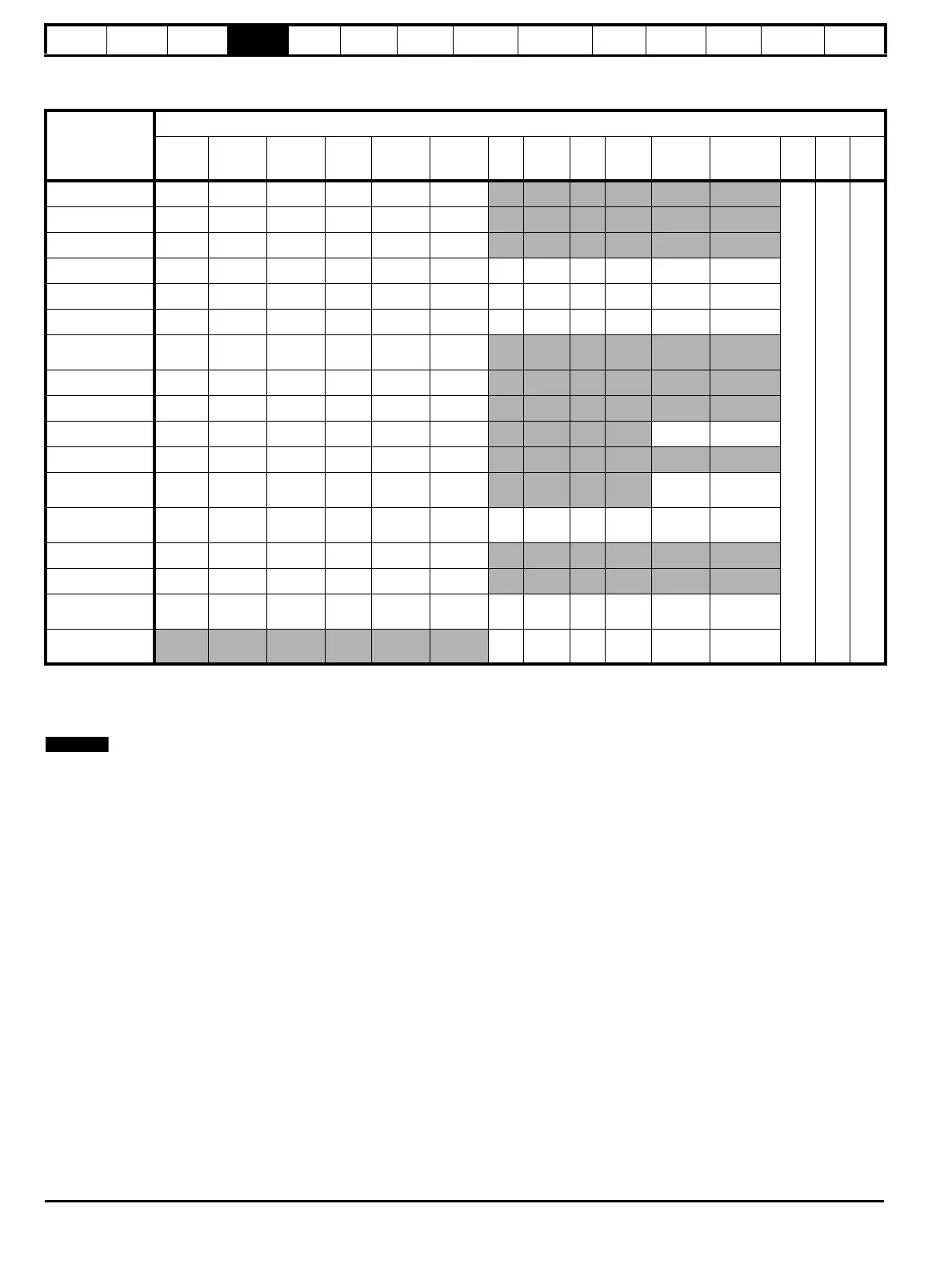
4.15.3 Position feedback connection details
Table 4-28 P1 Position feedback connection details
*1 - One sine wave per revolution
*2 - One cosine wave per revolution
Greyed cells are for P2 position feedback connections or simulated encoder outputs.
Freeze and Freeze\ on terminals 5 and 6 are for Freeze input 1. Freeze2 and Freeze2\ on terminals 11 and 12 are for Freeze input 2.
P1 Position
feedback
interface
Pr 03.038
Connections
1 2 3 4 5 6 7 8 9 10 11 12 13 14 15
AB (0) A A\ B B\ Z Z\
+V 0V Th
FD (1) F F\ D D\ Z Z\
FR (2) F F\ R R\ Z Z\
AB Servo (3) A A\ B B\ Z Z\ U U\ V V\ W W\
FD Servo (4) F F\ D D\ Z Z\ U U\ V V\ W W\
FR Servo (5) F F\ R R\ Z Z\ U U\ V V\ W W\
SC (6)
A
(Cos)
A\
(Cos\)
B
(Sin)
B\
(Sin\)
ZZ\
SC Hiperface (7) Cos Cosref Sin Sinref DATA DATA\
EnDat (8) DATA DATA\ CLK CLK\ Freeze Freeze\
SC EnDat (9) A A\ B B\ DATA DATA\ CLK CLK\
SSI (10) DATA DATA\ CLK CLK\ Freeze Freeze\
SC SSI (11)
A
(Cos)
A\
(Cos\)
B
(Sin)
B\
(Sin\)
DATA DATA\
CLK CLK\
SC Servo (12)
A
(Cos)
A\
(Cos\)
B
(Sin)
B\
(Sin\)
ZZ\UU\VV\WW\
BiSS (13) DATA DATA\ CLK CLK\ Freeze Freeze\
Resolver (14) Cos H Cos L Sin H Sin L Ref H Ref L
SC SC (15)
A
(Cos)
A\
(Cos\)
B
(Sin)
B\
(Sin\)
ZZ\
C*
1
C\*
1
D*
2
D\*
2
Freeze2 Freeze2\
Commutation
Only (16)
UU\VV\ W W\

 Loading...


