Safety
information
Product
information
Mechanical
installation
Electrical
installation
Getting
started
Basic
parameters
Running
the motor
Optimization
NV Media Card
Operation
Onboard
PLC
Advanced
parameters
Technical
data
Diagnostics
UL listing
information
Unidrive M702 User Guide 43
Issue Number: 3
When designing an IP65 (NEMA 12) enclosure (Figure 3-30 Example of
IP65 (NEMA 12) through-panel layout on page 40), consideration should
be made to the dissipation from the front of the drive.
Table 3-6 Power losses from the front of the drive when through-
panel mounted
3.10 Heatsink mounted brake resistor
3.10.1 Size 3, 4 and 5 internal braking resistor
Size 3, 4 and 5 have been designed with an optional space-saving
heatsink mounted resistor. The resistor can be installed within the
heatsink fins of the drive. When the heatsink resistor is used, an external
thermal protection device is not required as the resistor is designed such
that it will fail safely under any fault conditions. The in-built software
overload protection is set-up at default to protect the resistor. The
resistor is rated to IP54 (NEMA 12).
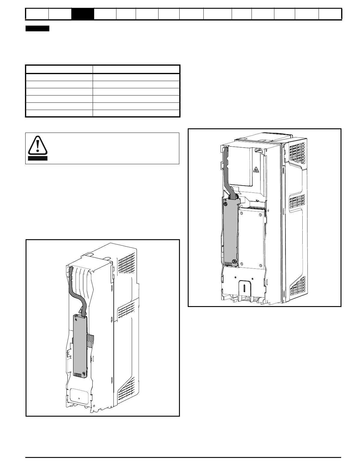
3.10.2 Internal braking resistor installation
instructions
Figure 3-36 Brake resistor installation on size 3
1. Remove the terminal covers as detailed in section 3.3.1 Removing
the terminal covers on page 22.
2. Remove the internal EMC filter as shown in section 4.12.2 Internal
EMC filter on page 70.
3. Remove the brake resistor bung from the hole in the chassis, the
closed end of the bung will need to be pierced so that the cable has
access to be routed through.
4. Feed brake resistor bung onto outer insulation of brake resistor
cable. The wider end of the bung should be inserted first. The
Narrow end should align with end of insulation.
5. Install the braking resistor to the heatsink using captive screws. The
screws should be tighten to a maximum torque of 2 N m (1.5 lb ft).
6. Route the cables through the provided hole at the rear of the
heatsink as shown in Figure 3-36 and take the cable out from the
front side of the drive. Ensure the cables are routed between the fins
of the heatsink.
7. Crimp the cable ends and make appropriate connections. The brake
terminals must be tightened to a maximum torque of 2 N m (1.5 Ib ft).
8. Replace the terminal covers on the drive, tighten to a maximum
torque of 1 N m (0.7 lb ft).
Figure 3-37 Brake resistor installation on size 4
1. Remove the terminal covers as detailed in section 3.3.1 Removing
the terminal covers on page 22.
2. Remove the brake resistor bung from the hole in the chassis, the
closed end of the bung will need to be pierced so that the cable has
access to be routed through.
3. Feed brake resistor bung onto outer insulation of brake resistor
cable. The wider end of the bung should be inserted first. The
Narrow end should align with end of insulation.
4. Install the braking resistor to the heatsink using captive screws as
shown in Figure 3-37. The screws should be tighten to a maximum
torque of 2 N m (1.5 lb ft).
5. Route the cables through the provided hole at the rear of the
heatsink as shown in Figure 3-37 and take the cable out from the
front side of the drive. Ensure the cables are routed between the
tabs of the heatsink, and the cables are not trapped between the
heatsink fins and the resistor.
6. Crimp the cable ends and make appropriate connections. The brake
terminals must be tightened to a maximum torque of 2 N m (1.5 Ib
ft).
7. Replace the terminal covers on the drive, tighten to a maximum
torque of 1 N m (0.7 lb ft).
Frame size Power loss
3
4
5
6
7
8
The internal / heatsink mounted braking resistors must only
be used with the following drives.
Brake resistor 1220-2752-00 must only be used with size 3
drives. Brake resistor 1299-0003-00 must only be used with
size 4 and 5 drives.

 Loading...


