Safety
information
Product
information
Mechanical
installation
Electrical
installation
Getting
started
Basic
parameters
Running
the motor
Optimization
NV Media Card
Operation
Onboard
PLC
Advanced
parameters
Technical
data
Diagnostics
UL listing
information
Unidrive M702 User Guide 65
Issue Number: 3
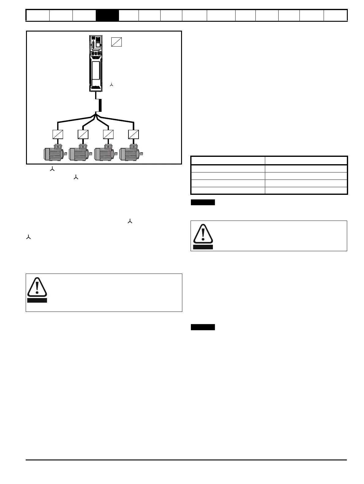
Figure 4-17 Alternative connection for multiple motors
4.9.5 / Δ motor operation
The voltage rating for
and Δ connections of the motor should always
be checked before attempting to run the motor.
The default setting of the motor rated voltage parameter is the same as
the drive rated voltage, i.e.
400 V drive 400 V rated voltage
230 V drive 230 V rated voltage
A typical 3 phase motor would be connected in
for 400 V operation or
Δ for 230 V operation, however, variations on this are common e.g.
690 V
Δ 400 V.
Incorrect connection of the windings will cause severe under or over
fluxing of the motor, leading to a very poor output torque or motor
saturation and overheating respectively.
4.9.6 Output contactor
A contactor is sometimes required to be installed between the drive and
motor for safety purposes.
The recommended motor contactor is the AC3 type.
Switching of an output contactor should only occur when the output of
the drive is disabled.
Opening or closing of the contactor with the drive enabled will lead to:
1. OI ac trips (which cannot be reset for 10 seconds)
2. High levels of radio frequency noise emission
3. Increased contactor wear and tear
The Drive Enable terminal (terminal 11 and terminal 13) when opened
provides a SAFE TORQUE OFF function. This can in many cases
replace output contactors.
For further information see section 4.16 SAFE TORQUE OFF (STO) on
page 86.
4.10 Braking
Braking occurs when the drive is decelerating the motor, or is preventing
the motor from gaining speed due to mechanical influences. During
braking, energy is returned to the drive from the motor.
When motor braking is applied by the drive, the maximum regenerated
power that the drive can absorb is equal to the power dissipation
(losses) of the drive.
When the regenerated power is likely to exceed these losses, the DC
bus voltage of the drive increases. Under default conditions, the drive
brakes the motor under PI control, which extends the deceleration time
as necessary in order to prevent the DC bus voltage from rising above a
user defined set-point.
If the drive is expected to rapidly decelerate a load, or to hold back an
overhauling load, a braking resistor must be installed.
Table 4-17 shows the default DC voltage level at which the drive turns on
the braking transistor. However the braking resistor turn on and the turn
off voltages are programmable with Braking IGBT Lower Threshold
(06.073) and Braking IGBT Upper Threshold (06.074).
Table 4-17 Default braking transistor turn on voltage
N
When a braking resistor is used, Pr 00.015 should be set to Fast ramp
mode.
4.10.1 Heatsink mounted braking resistor
A resistor has been especially designed to be mounted within the
heatsink of the drive (size 3, 4 and 5). See section 3.10 Heatsink
mounted brake resistor on page 43 for mounting details. The design of
the resistor is such that no thermal protection circuit is required, as the
device will fail safely under fault conditions. On size 3, 4 and 5 the in built
software overload protection is set-up at default for the designated
heatsink mounted resistor. The heatsink mounted resistor is not supplied
with the drive and can be purchased separately.
Table 4-18 provides the resistor data for each drive rating.
N
The internal / heatsink mounted resistor is suitable for applications with a
low level of regen energy only. See Table 4-18.
If the cable between the drive and the motor is to be
interrupted by a contactor or circuit breaker, ensure that the
drive is disabled before the contactor or circuit breaker is
opened or closed. Severe arcing may occur if this circuit is
interrupted with the motor running at high current and low
speed.
connection
Inductor
Motor protection
relay
Drive voltage rating DC bus voltage level
200 V 390 V
400 V 780 V
575 V 930 V
690 V 1120 V
High temperatures
Braking resistors can reach high temperatures. Locate
braking resistors so that damage cannot result. Use cable
having insulation capable of withstanding high temperatures.

 Loading...


