Safety
information
Product
information
Mechanical
installation
Electrical
installation
Getting
started
Basic
parameters
Running
the motor
Optimization
NV Media Card
Operation
Onboard
PLC
Advanced
parameters
Technical
data
Diagnostics
UL listing
information
48 Unidrive M702 User Guide
Issue Number: 3
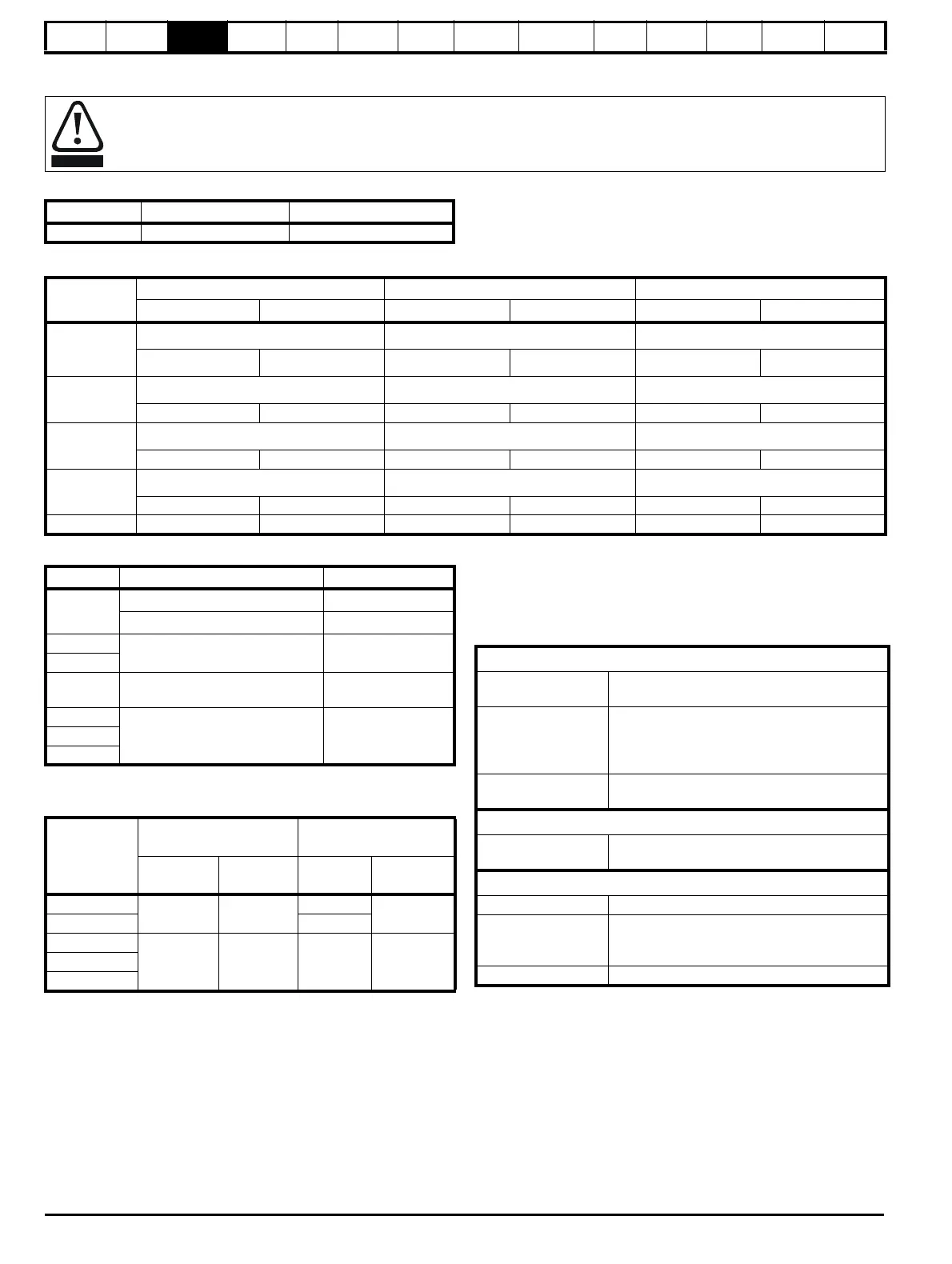
3.12.2 Terminal sizes and torque settings
Table 3-14 Drive control and relay terminal data
Table 3-15 Drive power terminal data
Table 3-16 Plug-in terminal block maximum cable sizes
Table 3-17 External EMC filter terminal data
3.13 Routine maintenance
The drive should be installed in a cool, clean, well ventilated location.
Contact of moisture and dust with the drive should be prevented.
Regular checks of the following should be carried out to ensure drive /
installation reliability are maximized:
To avoid a fire hazard and maintain validity of the UL listing, adhere to the specified tightening torques for the power and ground
terminals. Refer to the following tables.
Model Connection type Torque setting
All Plug-in terminal block 0.5 N m (0.4 lb ft)
Unidrive M
frame size
AC and motor terminals DC and braking Ground terminal
Recommended Maximum Recommended Maximum Recommended Maximum
3 and 4
Plug-in terminal block
T20 Torx (M4) T20 Torx (M4) / M4 Nut (7 mm AF)
0.7 N m (0.5 lb ft)
0.8 N m (0.6 lb ft) 2.0 N m (1.4 Ib ft) 2.5 N m (1.8 Ib ft) 2.0 N m (1.4 Ib ft) 2.5 N m (1.8 Ib ft)
5
Plug-in terminal block
T20 Torx (M4) / M4 Nut (7 mm AF) T20 Torx (M4) / M4 Nut (7 mm AF)
1.5 N m (1.1 lb ft) 1.8 N m (1.3 lb ft)
1.5 N m (1.1 Ib ft) 2.5 N m (1.8 Ib ft)
2.0 N m (1.4 Ib ft) 5.0 N m (3.7 Ib ft)
6
M6 Nut (10 mm AF) M6 Nut (10 mm AF) M6 Nut (10 mm AF)
6.0 N m(4.4 Ib ft) 8.0 N m(6.0 Ib ft) 6.0 N m(4.4 Ib ft) 8.0 N m(6.0 Ib ft) 6.0 N m(4.4 Ib ft) 8.0 N m(6.0 Ib ft)
7
M8 Nut (13 mm AF) M8 Nut (13 mm AF) M8 Nut (13 mm AF)
12 N m (8.8 Ib ft) 14 N m (10.0 Ib ft) 12 N m (8.8 Ib ft) 14 N m (10.0 Ib ft) 12 N m (8.8 Ib ft) 14 N m (10.0 Ib ft)
8
Model size Terminal block description Max cable size
All
11 way control connectors
1.5 mm
2
(16 AWG)
2 way relay connector
2.5 mm
2
(12 AWG)
3
6 way AC power connector
6 mm
2
(10 AWG)
4
5
3 way AC power connector
3 way motor connector
8 mm
2
(8 AWG)
6
2 way low voltage power
24 V supply connector
1.5 mm
2
(16 AWG)
7
8
CT part
number
Power
connections
Ground
connections
Max cable
size
Max torque
Ground
stud size
Max torque
4200-3230
4 mm
2
(12 AWG)
0.8 N m
(0.59 lb ft)
M5
3.0 N m
(2.2 lb ft)
4200-3480 M5
4200-2300
16 mm
2
(6 AWG)
2.3 N m
(1.70 Ib ft)
M6
4.8 N m
(2.8 lb ft)
4200-4500
4200-3690
Environment
Ambient temperature
Ensure the enclosure temperature remains at or
below maximum specified
Dust
Ensure the drive remains dust free – check that
the heatsink and drive fan are not gathering
dust. The lifetime of the fan is reduced in dusty
environments.
Moisture
Ensure the drive enclosure shows no signs of
condensation
Enclosure
Enclosure door filters
Ensure filters are not blocked and that air is free
to flow
Electrical
Screw connections Ensure all screw terminals remain tight
Crimp terminals
Ensure all crimp terminals remains tight – check
for any discoloration which could indicate
overheating
Cables Check all cables for signs of damage

 Loading...


