Safety
information
Product
information
Mechanical
installation
Electrical
installation
Getting
started
Basic
parameters
Running
the motor
Optimization
NV Media Card
Operation
Onboard
PLC
Advanced
parameters
Technical
data
Diagnostics
UL listing
information
Unidrive M702 User Guide 55
Issue Number: 3
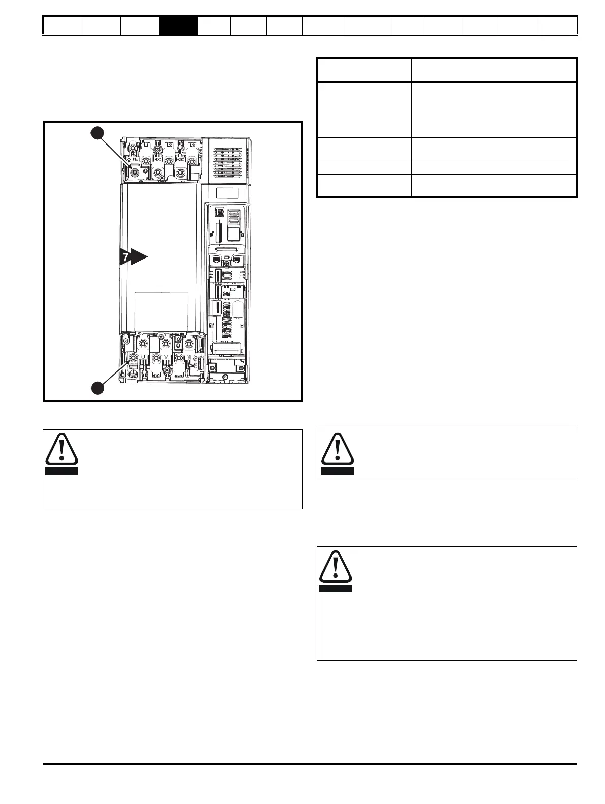
Size 7
On size 7, the supply and motor ground connections are made using the
M8 studs located by the supply and motor connection terminals.
Size 8
On size 8, the supply and motor ground connections are made using the
M10 studs located by the supply and motor connection terminals.
Figure 4-9 Size 7 and 8 ground connections
1. Ground connection studs.
Table 4-1 Protective ground cable ratings
4.2 AC supply requirements
Voltage:
200 V drive: 200 V to 240 V ±10 %
400 V drive: 380 V to 480 V ±10 %
575 V drive: 500 V to 575 V ±10 %
690 V drive: 500 V to 690 V ±10 %
Number of phases: 3
Maximum supply imbalance: 2 % negative phase sequence (equivalent
to 3 % voltage imbalance between phases).
Frequency range: 45 to 66 Hz
For UL compliance only, the maximum supply symmetrical fault current
must be limited to 100 kA
4.2.1 Supply types
All drives are suitable for use on any supply type i.e TN-S, TN-C-S, TT
and IT.
• Supplies with voltage up to 600 V may have grounding at any
potential, i.e. neutral, centre or corner (“grounded delta”)
• Supplies with voltage above 600 V may not have corner grounding
Drives are suitable for use on supplies of installation category III and
lower, according to IEC60664-1. This means they may be connected
permanently to the supply at its origin in a building, but for outdoor
installation additional over-voltage suppression (transient voltage surge
suppression) must be provided to reduce category IV to category III.
A ground fault in the supply has no effect in any case. If the motor must
continue to run with a ground fault in its own circuit then an input
isolating transformer must be provided and if an EMC filter is required it
must be located in the primary circuit.
Unusual hazards can occur on ungrounded supplies with more than one
source, for example on ships. Contact the supplier of the drive for more
information.
The ground loop impedance must conform to the
requirements of local safety regulations.
The drive must be grounded by a connection capable of
carrying the prospective fault current until the protective
device (fuse, etc.) disconnects the AC supply.
The ground connections must be inspected and tested at
appropriate intervals.
Input phase
conductor size
Minimum ground conductor size
≤ 10 mm
2
Either 10 mm
2
or two conductors of the
same cross-sectional area as the input
phase conductor (an additional ground
connection is provided on sizes 3, 4 and 5
for this purpose).
> 10 mm
2
and ≤ 16 mm
2
The same cross-sectional area as the input
phase conductor
> 16 mm
2
and ≤ 35 mm
2
16 mm
2
> 35 mm
2
Half of the cross-sectional area of the input
phase conductor
If an SI-Applications Plus or SI-Register module is installed in
the drive, then the drive must not be used on a corner-
grounded or centre-grounded delta supply if the supply
voltage is above 300 V. If this is required, please contact the
supplier of the drive for more information.
Operation with IT (ungrounded) supplies:
Special attention is required when using internal or external
EMC filters with ungrounded supplies, because in the event
of a ground (earth) fault in the motor circuit the drive may not
trip and the filter could be over-stressed. In this case, either
the filter must not be used (removed) or additional
independent motor ground fault protection must be provided.
For instructions on removal, refer to section 4.12.2 Internal
EMC filter on page 70.
For details of ground fault protection contact the supplier of
the drive.

 Loading...


