xiv
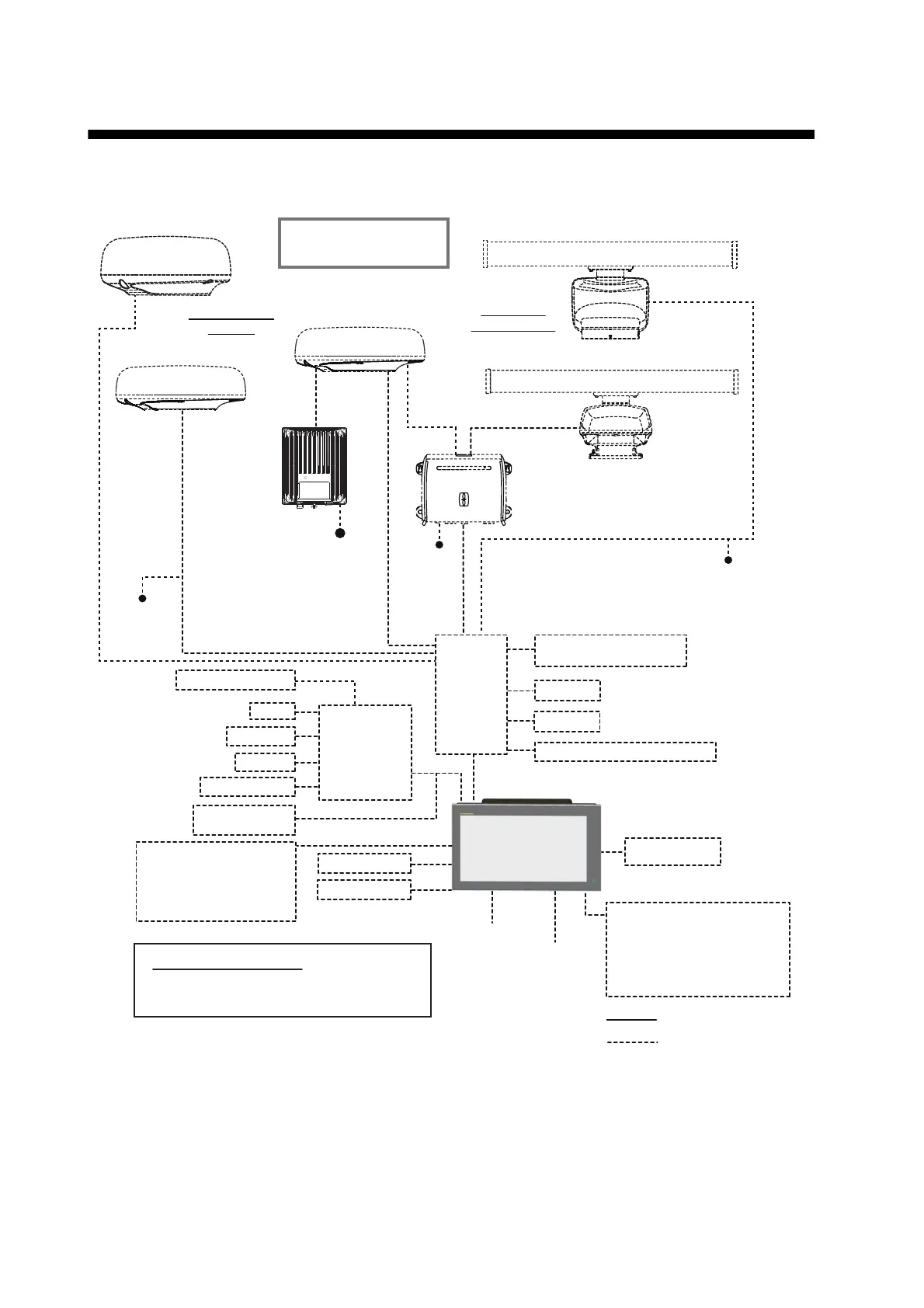
SYSTEM CONFIGURATION
Basic configuration is shown with solid lines. Optional equipment is denoted with dashed lines.
Note: When connecting an external monitor to the multi function display, use a monitor whose as-
pect ratio is the same as that of the multi function display (16:9). The pictures may be stretched
or shrunk with a different aspect ratio. Output to an HPD (Hot Plug Detect) monitor is not possible.
CCD Camera
CCD Camera
FI-5002
SC-30
GP-330B
NAVpilot-700
FI-50/70
IF-NMEA2K1/2
IF-NMEAFI
12/24 VDC
Event SW
External Buzzer
Operator Fitness
Power input for NMEA2000
NMEA0183 out
Echo Sounder
(BBDS1, DFF series)
Environmental category
Radar antenna: Exposed to the weather
All other units: Protected from the weather
AIS Transponder
*
1
Radar sensors other than the DRS4DL,
DRS4D-NXT and DRS6A
X-Class do not requires a power supply unit
.
*
2
FUSION Electronics MS-700 series only (as of 12/2014).
*
3
Max. 4 NavNet TZtouch2 units (connected via Ethernet hub).
HUB -101
FA-30/50
FAX-30
FUSION-Link Equipment*
2
Wide Monitor
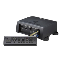
Remote Controller
MCU-002 or MCU-004
or
SD Card Unit SDU-001
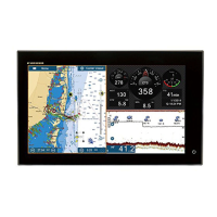
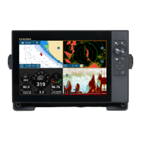
Multi Function Display*
3
TZTL12F
or
TZTL15F
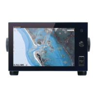
Multi Function Display*
3
TZTL12F
or
TZTL15F
Transducer
Open Array
Radar Sensors
12-24
VDC
DRS2D/DRS4D
POWER SUPPLY UNIT*
PSU-012/PSU-013
Radome Radar
Sensors
DRS4A/DRS6A/DRS12A/DRS25A
POWER
SUPPLY
UNIT*
PSU-017
For PSU-017
DRS4DL
12-24 VDC
DRS4D-NXT
24 VDC
12-24 VDC
Select one of radome
or open array sensor.
DRS6A X-Class
: Standard supply
: Optional or local
supply

 Loading...