GE Multilin T60 Transformer Protection System 5-41
5 SETTINGS 5.2 PRODUCT SETUP
5
The DNP binary outputs typically map one-to-one to IED data points. That is, each DNP binary output controls a single
physical or virtual control point in an IED. In the T60 relay, DNP binary outputs are mapped to virtual inputs. However, some
legacy DNP implementations use a mapping of one DNP binary output to two physical or virtual control points to support
the concept of trip/close (for circuit breakers) or raise/lower (for tap changers) using a single control point. That is, the DNP
master can operate a single point for both trip and close, or raise and lower, operations. The T60 can be configured to sup-
port paired control points, with each paired control point operating two virtual inputs. The
DNP NUMBER OF PAIRED CONTROL
POINTS
setting allows configuration of from 0 to 32 binary output paired controls. Points not configured as paired operate on
a one-to-one basis.
The
DNP TCP CONNECTION TIMEOUT setting specifies a time delay for the detection of dead network TCP connections. If
there is no data traffic on a DNP TCP connection for greater than the time specified by this setting, the connection will be
aborted by the T60. This frees up the connection to be re-used by a client.
Relay power must be re-cycled after changing the DNP TCP CONNECTION TIMEOUT setting for the changes to take
effect.
k) DNP / IEC 60870-5-104 POINT LISTS
PATH: SETTINGS PRODUCT SETUP COMMUNICATIONS DNP / IEC104 POINT LISTS
Up to 256 binary and up to 256 analog input points for the DNP protocol, or the MSP and MME points for IEC 60870-5-104
protocol, can be configured. The value for each point is user-programmable and can be configured by assigning FlexLogic
operands for binary inputs / MSP points or FlexAnalog parameters for analog inputs / MME points.
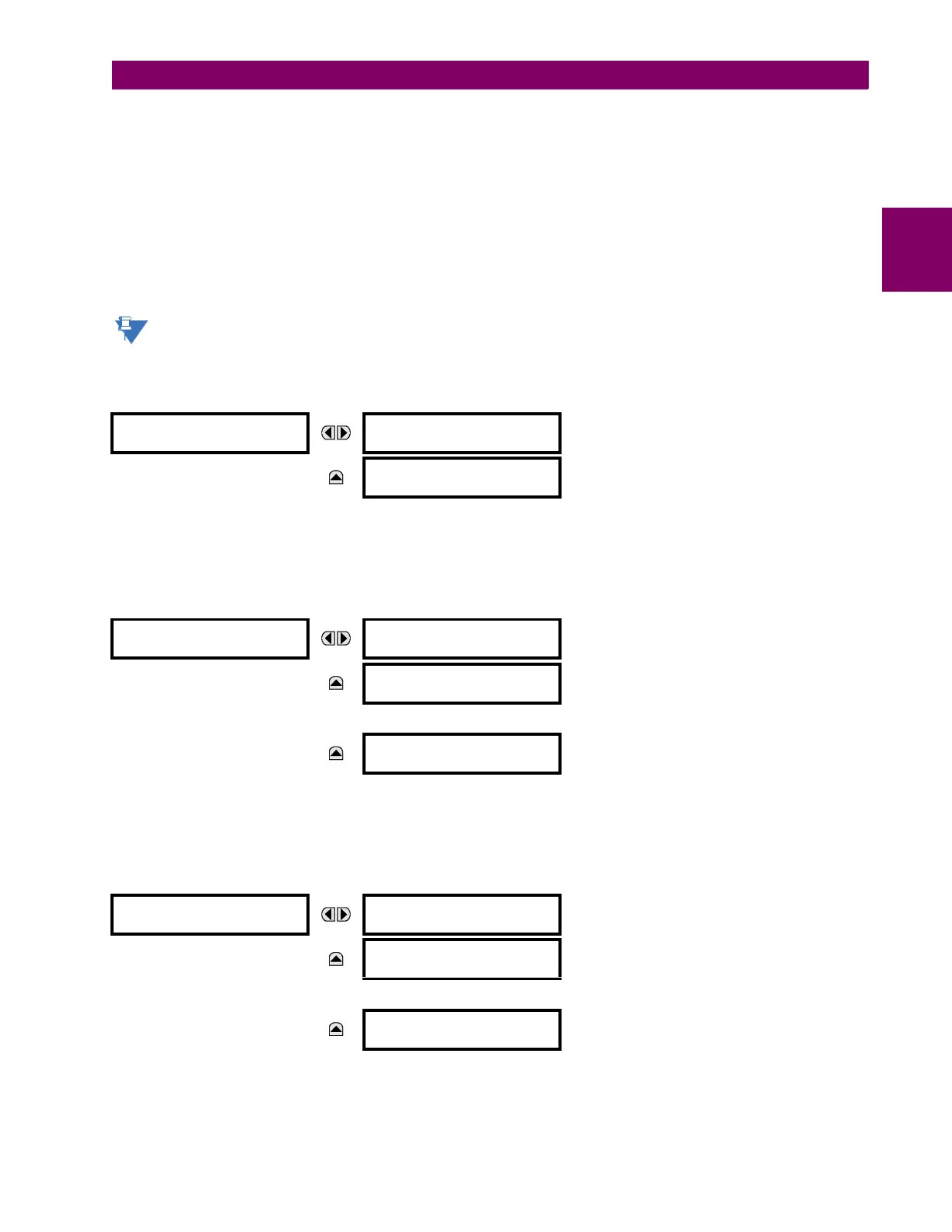
The menu for the binary input points (DNP) or MSP points (IEC 60870-5-104) is shown below.
PATH: SETTINGS PRODUCT SETUP COMMUNICATIONS DNP / IEC104 POINT LISTS BINARY INPUT / MSP POINTS
Up to 256 binary input points can be configured for the DNP or IEC 60870-5-104 protocols. The points are configured by
assigning an appropriate FlexLogic operand. See the Introduction to FlexLogic section in this chapter for the full range of
assignable operands.
The menu for the analog input points (DNP) or MME points (IEC 60870-5-104) is shown below.
PATH: SETTINGS PRODUCT SETUP COMMUNICATIONS DNP / IEC104 POINT LISTS ANALOG INPUT / MME POINTS
Up to 256 analog input points can be configured for the DNP or IEC 60870-5-104 protocols. The analog point list is config-
ured by assigning an appropriate FlexAnalog parameter to each point. Refer to Appendix A: FlexAnalog Parameters for the
full range of assignable parameters.
DNP / IEC104
POINT LISTS
BINARY INPUT / MSP
POINTS
Range: see sub-menu below
MESSAGE
ANALOG INPUT / MME
POINTS
Range: see sub-menu below
BINARY INPUT / MSP
POINTS
Point: 0
Off
Range: FlexLogic operand
MESSAGE
Point: 1
Off
Range: FlexLogic operand
MESSAGE
Point: 255
Off
Range: FlexLogic operand
ANALOG INPUT / MME
POINTS
Point: 0
Off
Range: any FlexAnalog parameter
MESSAGE
Point: 1
Off
Range: any FlexAnalog parameter
MESSAGE
Point: 255
Off
Range: any FlexAnalog parameter
 Loading...


