5-212 T60 Transformer Protection System GE Multilin
5.6 GROUPED ELEMENTS 5 SETTINGS
5
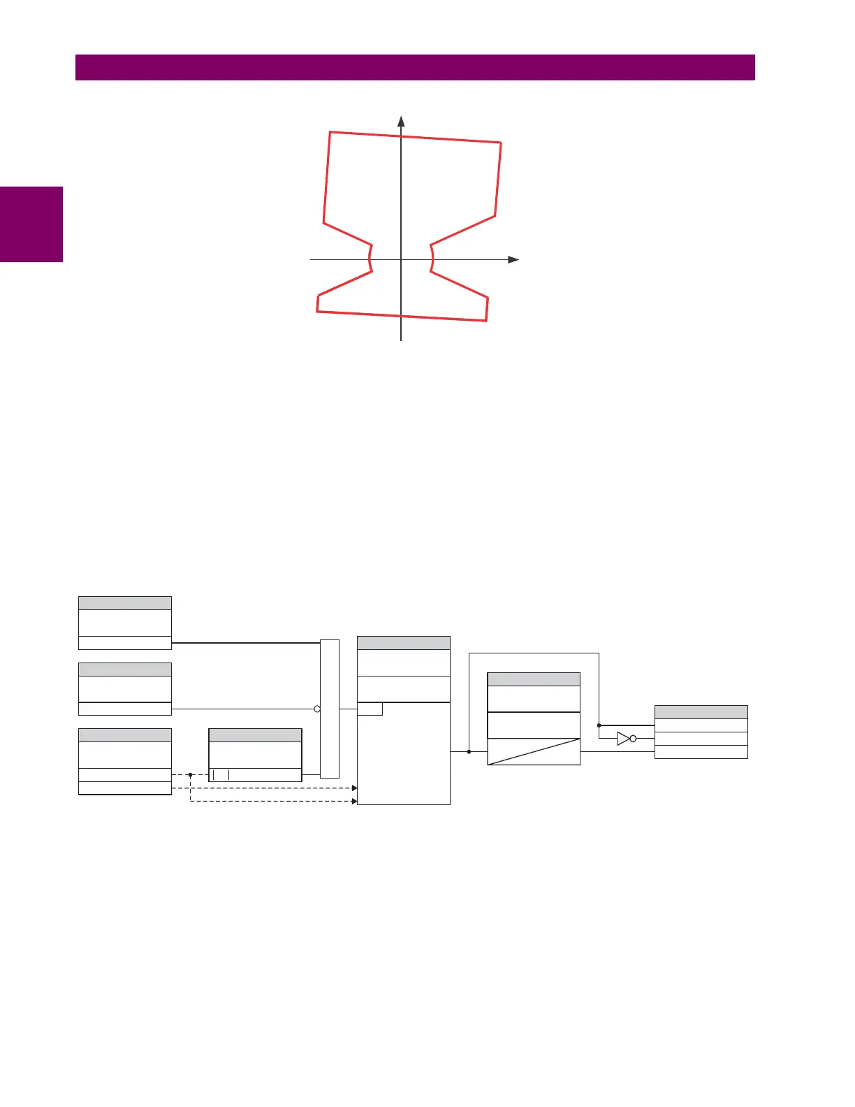
Figure 5–97: LOAD ENCROACHMENT APPLIED TO DISTANCE ELEMENT
• LOAD ENCROACHMENT MIN VOLT: This setting specifies the minimum positive-sequence voltage required for oper-
ation of the element. If the voltage is below this threshold a blocking signal will not be asserted by the element. When
selecting this setting one must remember that the T60 measures the phase-to-ground sequence voltages regardless of
the VT connection.
The nominal VT secondary voltage as specified with the SYSTEM SETUP AC INPUTS VOLTAGE BANK X5 PHASE
VT SECONDARY setting is the per-unit base for this setting.
• LOAD ENCROACHMENT REACH: This setting specifies the resistive reach of the element as shown in the Load
encroachment characteristic diagram. This setting should be entered in secondary ohms and be calculated as the pos-
itive-sequence resistance seen by the relay under maximum load conditions and unity power factor.
• LOAD ENCROACHMENT ANGLE: This setting specifies the size of the blocking region as shown on the Load
encroachment characteristic diagram and applies to the positive-sequence impedance.
Figure 5–98: LOAD ENCROACHMENT SCHEME LOGIC
SETTING
SETTING
SETTING SETTING
SETTINGS
SETTINGS
FLEXLOGIC OPERANDS
LOAD ENCROACHMENT
FUNCTION:
LOAD ENCRMNT BLK:
LOAD ENCROACHMENT
SOURCE:
LOAD ENCROACHMENT
MIN VOLT:
LOAD ENCROACHMENT
RST DELAY:
LOAD ENCROACHMENT
PKP DELAY:
LOAD ENCROACHMENT
REACH:
LOAD ENCROACHMENT
ANGLE:
Load Encroachment
Characteristic
LOAD ENCHR OP
LOAD ENCHR DPO
LOAD ENCHR PKP
Off=0
Pos Seq Voltage (V_1) V_1 > Pickup
Pos Seq Current (I_1)
Enabled=1
827847A3.CDR
RUN
t
t
PKP
RST
AND
 Loading...


