GE Multilin T60 Transformer Protection System 5-81
5 SETTINGS 5.2 PRODUCT SETUP
5
When in the Disabled mode, minor alarms do not assert a FlexLogic operand, write to the event recorder, or display target
messages. Moreover, they do not trigger the ANY MINOR ALARM or ANY SELF-TEST messages. When in Enabled mode,
minor alarms continue to function along with other major and minor alarms. See the Relay Self-tests section in chapter 7 for
information on major and minor self-test alarms.
5.2.13 CONTROL PUSHBUTTONS
PATH: SETTINGS PRODUCT SETUP CONTROL PUSHBUTTONS CONTROL PUSHBUTTON 1(7)
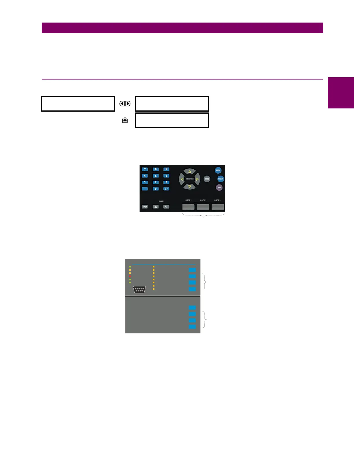
There are three standard control pushbuttons, labeled USER 1, USER 2, and USER 3, on the standard and enhanced front
panels. These are user-programmable and can be used for various applications such as performing an LED test, switching
setting groups, and invoking and scrolling though user-programmable displays.
The location of the control pushbuttons are shown in the following figures.
Figure 5–12: CONTROL PUSHBUTTONS (ENHANCED FACEPLATE)
An additional four control pushbuttons are included on the standard faceplate when the T60 is ordered with the 12 user-pro-
grammable pushbutton option.
Figure 5–13: CONTROL PUSHBUTTONS (STANDARD FACEPLATE)
Control pushbuttons are not typically used for critical operations and are not protected by the control password. However,
by supervising their output operands, the user can dynamically enable or disable control pushbuttons for security reasons.
Each control pushbutton asserts its own FlexLogic operand. These operands should be configured appropriately to perform
the desired function. The operand remains asserted as long as the pushbutton is pressed and resets when the pushbutton
is released. A dropout delay of 100 ms is incorporated to ensure fast pushbutton manipulation will be recognized by various
features that may use control pushbuttons as inputs.
An event is logged in the event record (as per user setting) when a control pushbutton is pressed. No event is logged when
the pushbutton is released. The faceplate keys (including control keys) cannot be operated simultaneously – a given key
must be released before the next one can be pressed.
CONTROL
PUSHBUTTON 1
CONTROL PUSHBUTTON 1
FUNCTION: Disabled
Range: Disabled, Enabled
MESSAGE
CONTROL PUSHBUTTON 1
EVENTS: Disabled
Range: Disabled, Enabled
Control pushbuttons
842813A1.CDR
842733A2.CDR
PICKUP
ALARM
TRIP
TEST MODE
TROUBLE
IN SERVICE
STATUS
USER 3
USER 2
USER 1
RESET
EVENT CAUSE
NEUTRAL/GROUND
PHASE C
PHASE B
PHASE A
OTHER
FREQUENCY
CURRENT
VOLTAGE
THREE
STANDARD
CONTROL
PUSHBUTTONS
USER 7
USER 6
USER 5
USER 4
FOUR EXTRA
OPTIONAL
CONTROL
PUSHBUTTONS
 Loading...


