6-20 T60 Transformer Protection System GE Multilin
6.3 METERING 6 ACTUAL VALUES
6
The metered values for real, reactive, and apparent power, as well as power factor, are displayed in this menu. The "SRC
1" text will be replaced by whatever name was programmed by the user for the associated source (see
SETTINGS SYS-
TEM SETUP SIGNAL SOURCES).
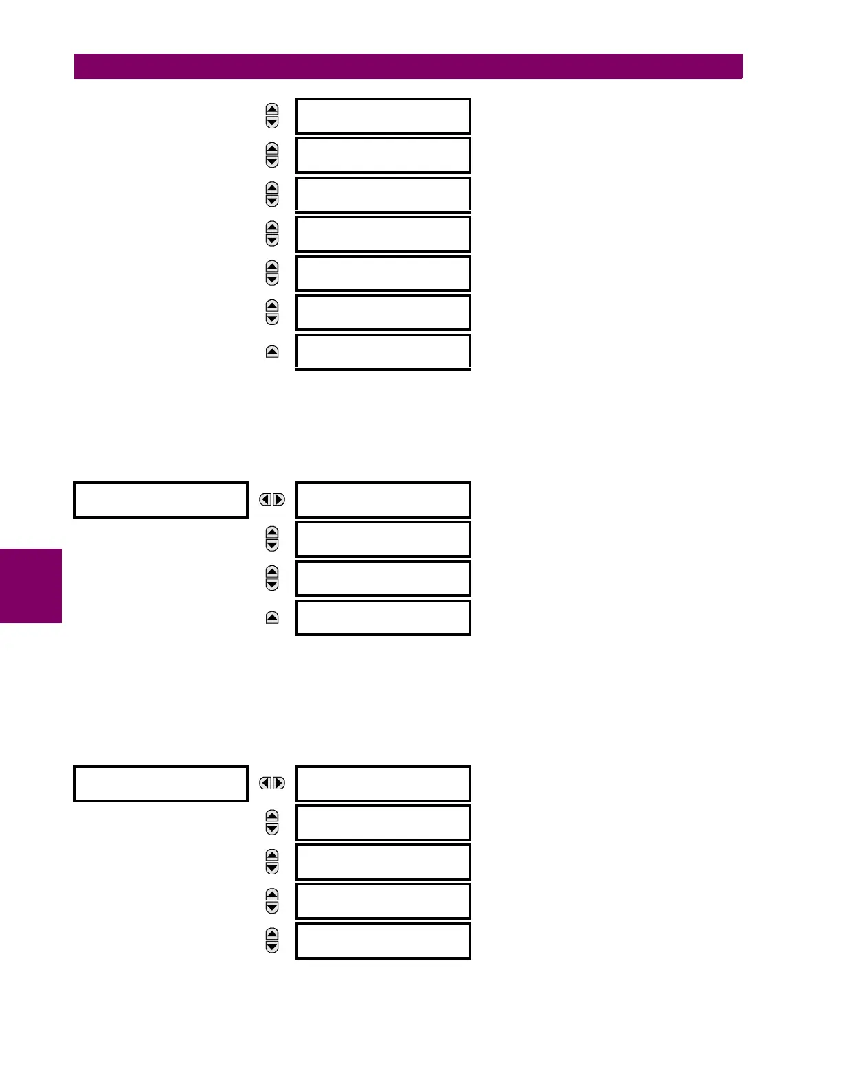
g) ENERGY METERING
PATH: ACTUAL VALUES METERING SOURCE SRC 1 ENERGY
The metered values for real and reactive energy are displayed in this menu. The "SRC 1" text will be replaced by whatever
name was programmed by the user for the associated source (see SETTINGS SYSTEM SETUP SIGNAL SOURCES).
Because energy values are accumulated, these values should be recorded and then reset immediately prior to changing
CT or VT characteristics.
h) DEMAND METERING
PATH: ACTUAL VALUES METERING SOURCE SRC 1 DEMAND
MESSAGE
SRC 1 APPARENT PWR
a: 0.000 VA
MESSAGE
SRC 1 APPARENT PWR
b: 0.000 VA
MESSAGE
SRC 1 APPARENT PWR
c: 0.000 VA
MESSAGE
SRC 1 POWER FACTOR
3: 1.000
MESSAGE
SRC 1 POWER FACTOR
a: 1.000
MESSAGE
SRC 1 POWER FACTOR
b: 1.000
MESSAGE
SRC 1 POWER FACTOR
c: 1.000
ENERGY
SRC 1
SRC 1 POS WATTHOUR:
0.000 Wh
MESSAGE
SRC 1 NEG WATTHOUR:
0.000 Wh
MESSAGE
SRC 1 POS VARHOUR:
0.000 varh
MESSAGE
SRC 1 NEG VARHOUR:
0.000 varh
DEMAND
SRC 1
SRC 1 DMD IA:
0.000 A
MESSAGE
SRC 1 DMD IA MAX:
0.000 A
MESSAGE
SRC 1 DMD IA DATE:
2001/07/31 16:30:07
MESSAGE
SRC 1 DMD IB:
0.000 A
MESSAGE
SRC 1 DMD IB MAX:
0.000 A
 Loading...


