5-144 T60 Transformer Protection System GE Multilin
5.4 SYSTEM SETUP 5 SETTINGS
5
• PMU 1 VA... IG CALIBRATION MAGNITUDE: These settings recognize applications with protection class voltage and
current sources, and allow the user to calibrate each channel (four voltages and four currents) individually to offset
errors introduced by VTs, CTs. The setting values are effectively a multiplier of the measured magnitudes. Therefore,
enter a multiplier greater than 100% of the secondary signal increases the true signal; and a multiplier less than 100%
value of the secondary signal reduces the true signal.
• PMU 1 SEQ VOLT SHIFT ANGLE: This setting allows correcting positive- and negative-sequence voltages for vector
groups of power transformers located between the PMU voltage point, and the reference node. This angle is effectively
added to the positive-sequence voltage angle, and subtracted from the negative-sequence voltage angle. Note that:
1. When this setting is not “0°”, the phase and sequence voltages do not agree. Unlike sequence voltages, the phase
voltages cannot be corrected in a general case, and therefore are reported as measured.
2. When receiving synchrophasor data at multiple locations, with possibly different reference nodes, it can be more
beneficial to allow the central locations to perform the compensation of sequence voltages.
3. This setting applies to PMU data only. The T60 calculates symmetrical voltages independently for protection and
control purposes without applying this correction.
4. When connected to line-to-line voltages, the PMU calculates symmetrical voltages with the reference to the AG
voltage, and not to the physically connected AB voltage (see the Metering Conventions section in Chapter 6).
• PMU 1 SEQ CURR SHIFT ANGLE: This setting allows correcting positive and negative-sequence currents for vector
groups of power transformers located between the PMU current point and the reference node. The setting has the
same meaning for currents as the
PMU 1 SEQ VOLT SHIFT ANGLE setting has for voltages. Normally, the two correcting
angles are set identically, except rare applications when the voltage and current measuring points are located at differ-
ent windings of a power transformer.
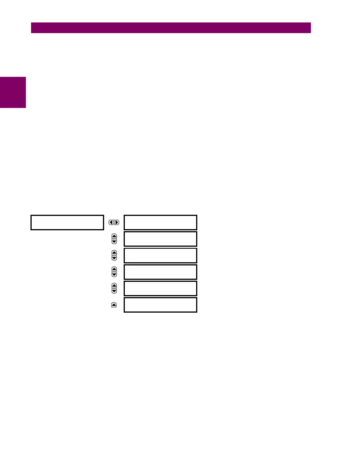
d) PMU TRIGGERING OVERVIEW
PATH: SETTINGS SYSTEM SETUP PHASOR... PHASOR MEASUREMENT UNIT 1 PMU 1 TRIGGERING
Each logical phasor measurement unit (PMU) contains five triggering mechanisms to facilitate triggering of the associated
PMU recorder, or cross-triggering of other PMUs of the system. They are:
• Overfrequency and underfrequency
• Overvoltage and undervoltage
•Overcurrent
• Overpower
• High rate of change of frequency
The pre-configured triggers can be augmented with a user-specified condition built freely using programmable logic of the
relay. The entire triggering logic is refreshed once every two power system cycles.
PMU 1
TRIGGERING
PMU 1 USER
TRIGGER
See page 5-145.
MESSAGE
PMU 1 FREQUENCY
TRIGGER
See page 5-145.
MESSAGE
PMU 1 VOLTAGE
TRIGGER
See page 5-146.
MESSAGE
PMU 1 CURRENT
TRIGGER
See page 5-147.
MESSAGE
PMU 1 POWER
TRIGGER
See page 5-148.
MESSAGE
PMU 1 df/dt
TRIGGER
See page 5-149.

 Loading...


