5-110 T60 Transformer Protection System GE Multilin
5.4 SYSTEM SETUP 5 SETTINGS
5
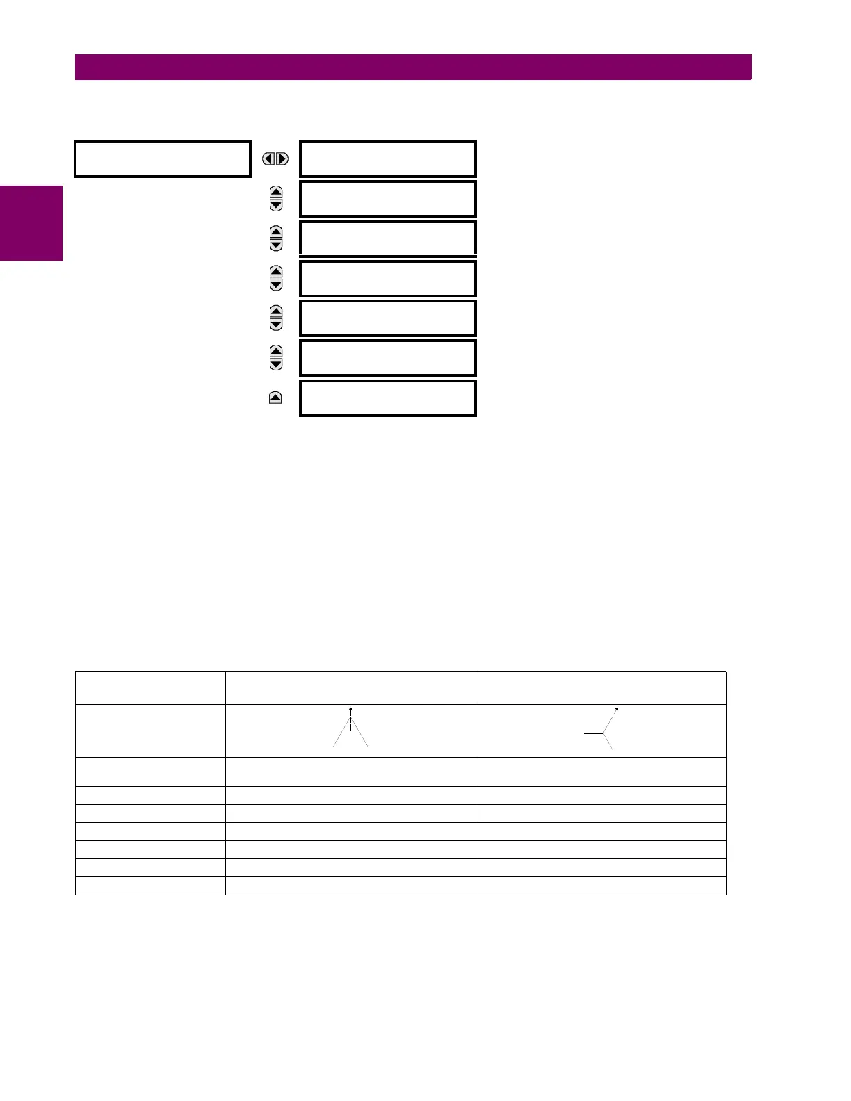
c) WINDINGS 1 TO 6
PATH: SETTINGS SYSTEM SETUP TRANSFORMER WINDING 1(6)
The settings specific to each winding are shown above.
Transformer differential protection uses the following calculated quantities (per phase): fundamental, second harmonic, and
fifth harmonic differential current phasors, and restraint current phasors. This information is extracted from the current
transformers (CTs) connected to the relay by correcting the magnitude and phase relationships of the currents for each
winding, so as to obtain zero (or near zero) differential currents under normal operating conditions. Traditionally, these cor-
rections were accomplished by interposing CTs and tapped relay windings with some combination of CT connections.
The T60 simplifies these configuration issues. All CTs at the transformer are connected wye (polarity markings pointing
away from the transformer). User-entered settings in the relay characterizing the transformer being protected and allow the
relay to automatically perform all necessary magnitude, phase angle, and zero-sequence compensation.
This section describes the algorithms in the relay that perform this compensation and produce the required calculated
quantities for transformer differential protection, by means of the following example of a delta-wye (-Y) connected power
transformer with the following data:
The abbreviated nomenclature for applicable relay settings is as follows:
Rotation =
SETTINGS SYSTEM SETUP POWER SYSTEM PHASE ROTATION
w
total
= SETTINGS SYSTEM SETUP TRANSFORMER GENERAL NUMBER OF WINDINGS
Compensation = SETTINGS SYSTEM SETUP TRANSFORMER GENERAL PHASE COMPENSATION
Source [w]= SETTINGS SYSTEM SETUP TRANSFORMER WINDING w WINDING w SOURCE
WINDING 1
WINDING 1 SOURCE:
SRC 1
Range: SRC 1, SRC 2, SRC 3, SRC 4, SRC 5, SRC 6
(or the user-defined name)
MESSAGE
WINDING 1 RATED MVA:
100.000 MVA
Range: 0.001 to 2000.000 MVA in steps of 0.001
MESSAGE
WINDING 1 NOM -
VOLTAGE: 220.000 kV
Range: 0.001 to 2000.000 kV in steps of 0.001
MESSAGE
WINDING 1
CONNECTION: Wye
Range: Wye, Delta, Zig-zag
MESSAGE
WINDING 1 GROUNDING:
Not within zone
Range: Not within zone, Within zone
MESSAGE
WINDING ~ ANGLE WRT
WINDING 1: 0.0°
Range: –359.9 to 0.0° in steps of 0.1, (‘~’ > 1)
(shown when viewed Winding is not Winding 1)
MESSAGE
WINDING 1 RESISTANCE
3: 10.0000 ohms
Range: 0.0001 to 100.0000 ohms in steps of 0.0001
Table 5–12: EXAMPLE DELTA-WYE CONNECTED POWER TRANSFORMER DATA
DATA WINDING 1
(DELTA) CONNECTION
WINDING 2
Y (WYE) CONNECTION
Voltage Phasor Diagram
Phase Shift 0° 30° lag (i.e. phases of wye winding lag
corresponding phases of delta winding by 30°)
Grounding In-zone grounding bank Ungrounded
Rated MVA 100/133/166 MVA 100/133/166 MVA
Nominal - Voltage 220 kV 69 kV
CT Connection Wye Wye
CT Ratio 500/5 1500/5
Auxiliary Cooling Two stages of forced air Two stages of forced air
 Loading...


