5-106 T60 Transformer Protection System GE Multilin
5.4 SYSTEM SETUP 5 SETTINGS
5
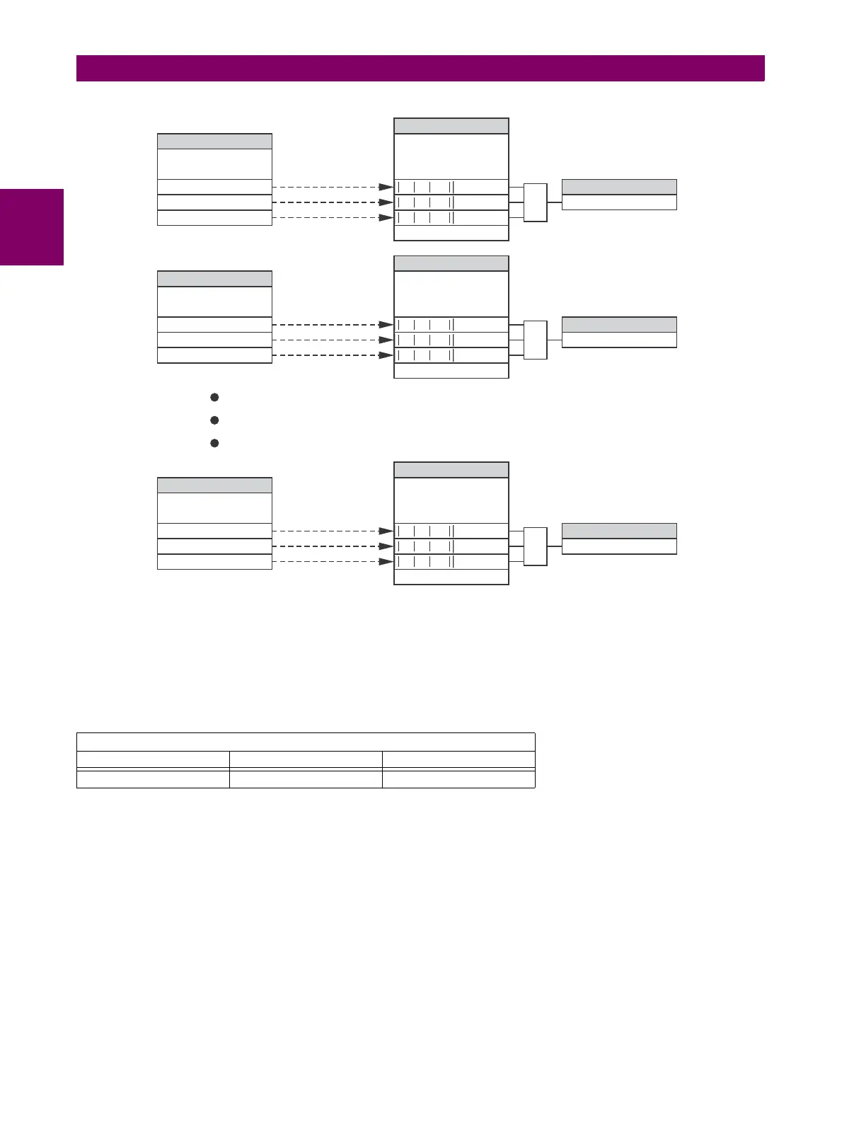
Figure 5–26: DISTURBANCE DETECTOR LOGIC DIAGRAM
The disturbance detector responds to the change in currents of twice the current cut-off level. The default cut-off threshold
is 0.02 pu; thus by default the disturbance detector responds to a change of 0.04 pu. The metering sensitivity setting (PROD-
UCT SETUP DISPLAY PROPERTIES CURRENT CUT-OFF LEVEL) controls the sensitivity of the disturbance detector
accordingly.
EXAMPLE USE OF SOURCES:
An example of the use of sources is shown in the diagram below. A relay could have the following hardware configuration:
This configuration could be used on a two-winding transformer, with one winding connected into a breaker-and-a-half sys-
tem. The following figure shows the arrangement of sources used to provide the functions required in this application, and
the CT/VT inputs that are used to provide the data.
INCREASING SLOT POSITION LETTER -->
CT/VT MODULE 1 CT/VT MODULE 2 CT/VT MODULE 3
CTs VTs not applicable
827092A3.CDR
SOURCE 1
CURRENT PHASOR
PRODUCT SETUP/DISPLAY
PROPERTIES/CURRENT
CUT-OFF LEVEL
PRODUCT SETUP/DISPLAY
PROPERTIES/CURRENT
CUT-OFF LEVEL
PRODUCT SETUP/DISPLAY
PROPERTIES/CURRENT
CUT-OFF LEVEL
SOURCE 2
CURRENT PHASOR
SOURCE 6
CURRENT PHASOR
ACTUAL
SETTING
SETTING
SETTING
ACTUAL
ACTUAL
FLEXLOGIC OPERAND
FLEXLOGIC OPERAND
FLEXLOGIC OPERAND
I_1
I_1
I_1
SRC 1 50DD OP
SRC 2 50DD OP
SRC 6 50DD OP
I_2
I_2
I_2
I_0
I_0
I_0
OR
OR
OR
Where ’ is 2 cycles oldI
Where ’ is 2 cycles oldI
Where ’ is 2 cycles oldI
II_1 - _1’ >2*CUT-OFF
II_1 - _1’ >2*CUT-OFF
II_1 - _1’ >2*CUT-OFF
II_2 - _2’ >2*CUT-OFF
II_2 - _2’ >2*CUT-OFF
II_2 - _2’ >2*CUT-OFF
II_0 - _0’ >2*CUT-OFF
II_0 - _0’ >2*CUT-OFF
II_0 - _0’ >2*CUT-OFF
 Loading...


