GE Multilin T60 Transformer Protection System 5-135
5 SETTINGS 5.4 SYSTEM SETUP
5
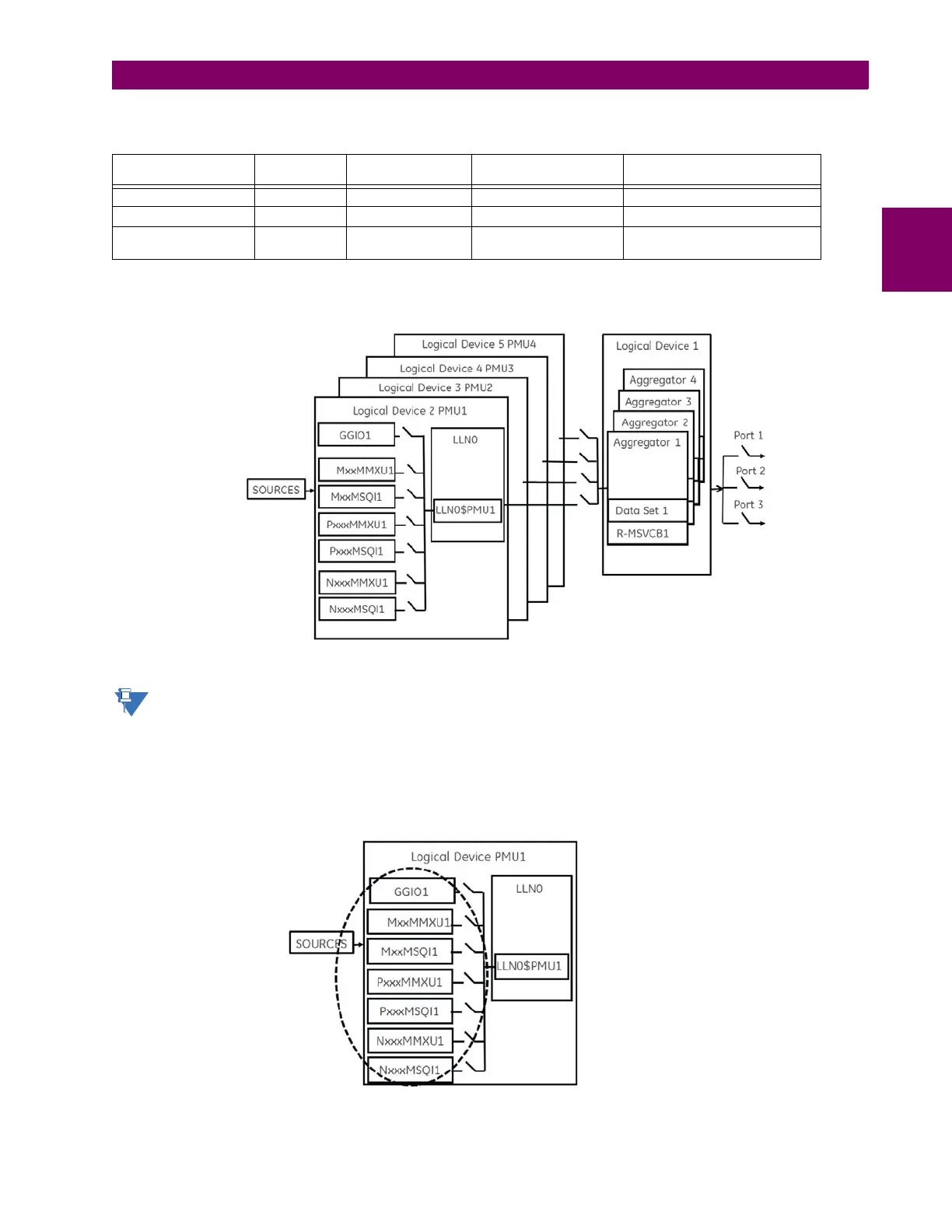
The number of PMUs and aggregators vary by product, as outlined in the table.
The figure shows an example of an N60 using four Logical Device PMUs (Logical Device 2 through 5) and four aggrega-
tors. The control blocks for the aggregators are located in LD1. A 64 char LDName setting is provided.
Figure 5–46: N60 EXAMPLE FOR FOUR LOGICAL DEVICE PMUS
Precise time input to the relay from the international time standard, via either IRIG-B or PTP, is vital for correct syn-
chrophasor measurement and reporting. For IRIG-B, a DC level shift IRIG-B receiver must be used for the phasor
measurement unit to output proper synchrophasor values.
Depending on the applied filter, the Synchrophasors that are produced by PMUs are classified as either P (protection) or M
(Measurement) class Synchrophasors. Synchrophasors available within the UR that have no filtering applied are classified
as NONE, which within the standard is classified as PRES OR UNKNOWN under the Calculation Method - ClcMth. Each
Logical Device PMU supports one MxxMMXU, MxxMSQI, PxxxMMXU , PxxxMSQI, NxxMMXU, and one NxxMSQI logical
node.
Figure 5–47: LOGICAL NODES SUPPORTED IN EACH LOGICAL DEVICE
Table 5–15: IMPLEMENTATION BY MODEL NUMBER
MODEL NUMBER OF
PMUS
NUMBER OF
AGGREGATORS
NUMBER OF ANALOG
INPUTS
COMMENT
N60 6 4 16 1, 2, 4, or 6 PMUs can be used
C60 2 2 16
D60, F60, G60, L30,
L90, T60
11 16
 Loading...


