5-248 T60 Transformer Protection System GE Multilin
5.6 GROUPED ELEMENTS 5 SETTINGS
5
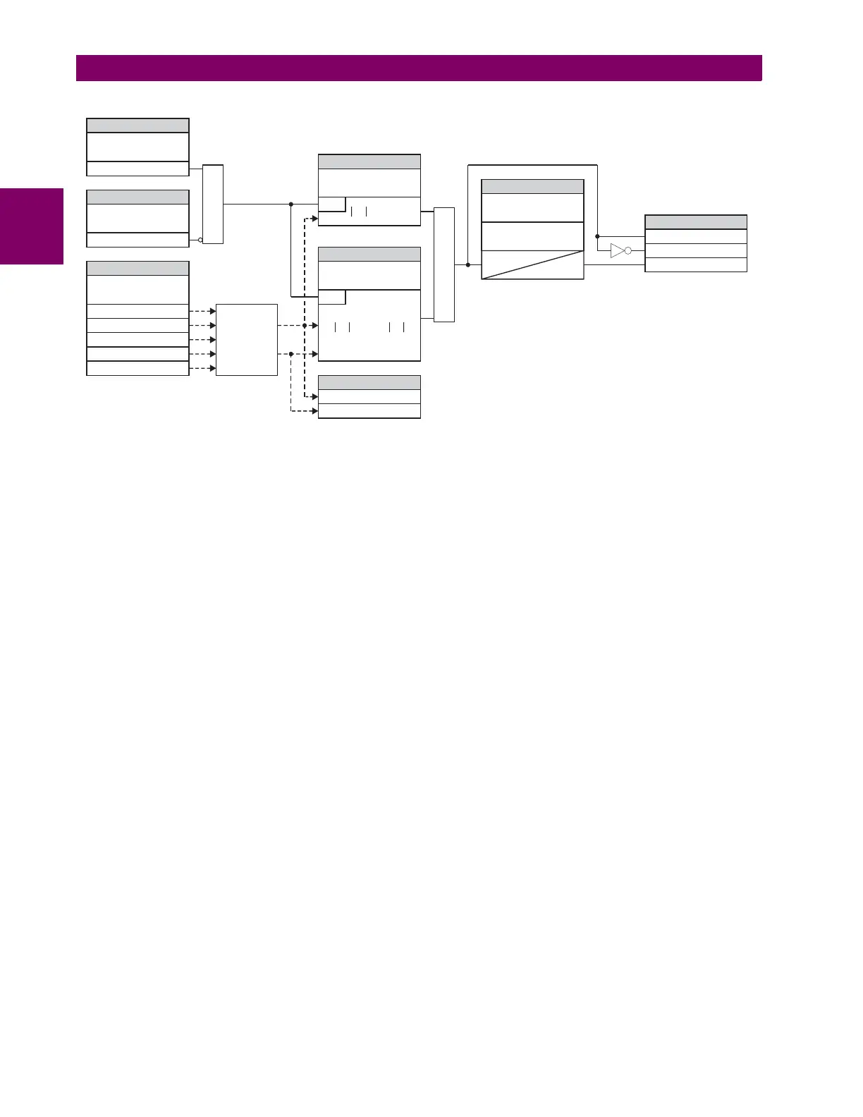
Figure 5–119: RESTRICTED GROUND FAULT SCHEME LOGIC
The following examples explain how the restraining signal is created for maximum sensitivity and security. These examples
clarify the operating principle and provide guidance for testing of the element.
EXAMPLE 1: EXTERNAL SINGLE-LINE-TO-GROUND FAULT
Given the following inputs: IA = 1 pu 0°, IB = 0, IC = 0, and IG = 1 pu180°
The relay calculates the following values:
Igd = 0, , , , and Igr = 2 pu
The restraining signal is twice the fault current. This gives extra margin should the phase or neutral CT saturate.
EXAMPLE 2: EXTERNAL HIGH-CURRENT SLG FAULT
Given the following inputs: IA = 10 pu 0°, IB = 0, IC = 0, and IG = 10 pu –180°
The relay calculates the following values:
Igd = 0, , , , and Igr = 20 pu.
EXAMPLE 3: EXTERNAL HIGH-CURRENT THREE-PHASE SYMMETRICAL FAULT
Given the following inputs: IA = 10 pu 0°, IB = 10 pu –120°, IC = 10 pu 120°, and IG = 0 pu
The relay calculates the following values:
Igd = 0, , , , and Igr = 10 pu.
EXAMPLE 4: INTERNAL LOW-CURRENT SINGLE-LINE-TO-GROUND FAULT UNDER FULL LOAD
Given the following inputs: IA = 1.10 pu 0°, IB = 1.0 pu –120°, IC = 1.0 pu 120°, and IG = 0.05 pu 0°
The relay calculates the following values:
I_0 = 0.033 pu 0°, I_2 = 0.033 pu 0°, and I_1 = 1.033 pu 0°
Igd = abs(3 0.0333 + 0.05) = 0.15 pu, IR0 = abs(3 0.033 – (0.05)) = 0.05 pu, IR2 = 3 0.033 = 0.10 pu,
IR1 = 1.033 / 8 = 0.1292 pu, and Igr = 0.1292 pu
Despite very low fault current level the differential current is above 100% of the restraining current.
SETTING
SETTING
SETTING
SETTING
SETTINGS
SETTING
FLEXLOGIC OPERANDS
ACTUAL VALUES
RESTD GND FT1
FUNCTION:
RESTD GND FT1
BLOCK:
RESTD GND FT1
SOURCE:
RESTD GND FT1
PICKUP:
RESTD GND FT1 RESET
DELAY:
RESTD GND FT1 PICKUP
DELAY:
RESTD GND FT1
SLOPE:
RESTD GND FT1 OP
RESTD GND FT1 DPO
RESTD GND FT1 PKP
RGF 1 Igd Mag
RGF 1 Igr Mag
Off=0
Enabled=1
AND
828002A3.CDR
RUN
RUN
Igd > PICKUP
IN
IG
I_0
I_1
I_2
AND
> SLOPE
*
Igd
Igr
Differential
and
Restraining
Currents
t
PKP
t
RST
IR0 abs 3
1
3
---
1––
2 pu==
IR1
13
8
----------
0.042 pu==
IR0 abs 3
1
3
---
10––
20 pu==
IR1 3
10
3
------
10
3
------
–
0==
IR0 abs 3 0 0–0 pu==
IR1 3
10
3
------
0–
10 pu==
 Loading...


