EasyManuals Logo
Home>GE>Relays>T60

GE T60 User Manual

GE T60
770 pages
To Next Page IconTo Next Page
To Previous Page IconTo Previous Page
Page #440 background imageLoading...
Page #440 background image
5-306 T60 Transformer Protection System GE Multilin
5.7 CONTROL ELEMENTS 5 SETTINGS
5
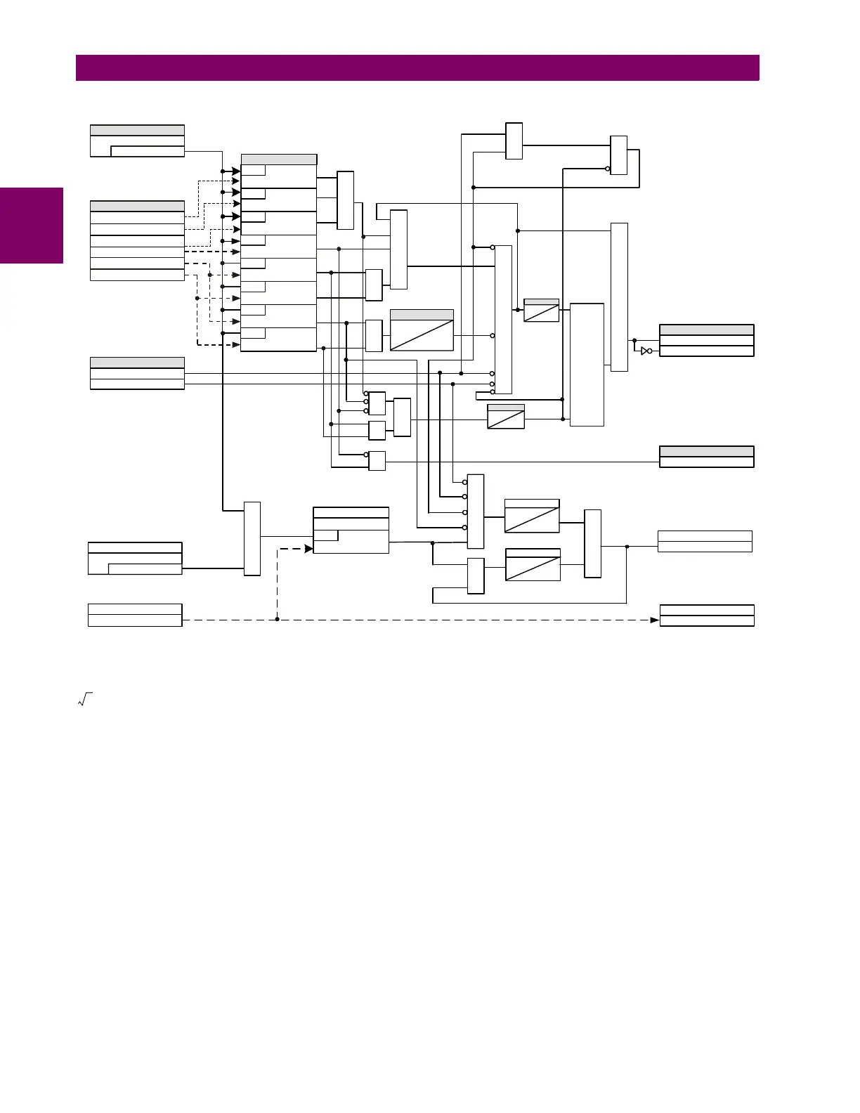
Figure 5–156: VT FUSE FAIL SCHEME LOGIC
Base voltage for this element is PHASE VT SECONDARY setting in the case of WYE VTs and (PHASE VT SECONDARY)/
in case of DELTA VTs.
827093AQ.CDR
FUSE
FAIL
FAULT
AND
AND
AND
SET
RESET
Reset-dominant
Latch
AND
AND
AND
AND
OR
OR
OR
OR
Function
SETTING
Enabled = 1
SOURCE 1
V_2
V_1
I_1
Run
V_1 < 0.05 pu
Run
V_2 > 0.1 pu
Run
I_1 > 0.075 pu
Run
V_1 < 0.80 pu
Run
I_1 < 0.05 pu
SRC1 50DD OP
FLEXLOGIC OPERANDS
2 cycles
20 cycles
SRC1 VT FUSE FAIL OP
FLEXLOGIC OPERANDS
SRC1 VT FUSE FAIL DPO
SRC1 VT FUSE FAIL VOL LOSS
FLEXLOGIC OPERAND
TIMER
OPEN POLE OP
The OPEN POLE OP operand applies
to the D60, L60, and L90
Neutral Wire Open Detect
SETTING
Enabled = 1
SOURCE 1
3V_0 (3rd Harmonic)
SETTING
Run
3V_0 3rd Harm >setting
3 HARM PKP
AND
SRC1 3V0 3nd Harmonic
FLEX-ANALOG
AND
5 cycles
0
TIMER
SRC1 VT NEU WIRE OPEN
FLEXLOGIC OPERAND
OR
AND
0
20 cycles
TIMER
2 cycles
0
TIMER
30 cycles
0
TIMER
COMPARATORS
VA
VB
VC
Run
|VB|-|VB| > 0.2 pu
& |VB| > 0.8 pu
Run
|VA|-|VA| > 0.2 pu
& |VA| > 0.8 pu
Run
|VC|-|VC| > 0.2 pu
& |VC| > 0.8 pu
OR
VA, VB and VC are the
voltage magnitude of one
cycle before
3

Table of Contents

Questions and Answers:

Question and Answer IconNeed help?

Do you have a question about the GE T60 and is the answer not in the manual?

GE T60 Specifications

General IconGeneral
BrandGE
ModelT60
CategoryRelays
LanguageEnglish

Related product manuals