3-26 T60 Transformer Protection System GE Multilin
3.3 DIRECT INPUT/OUTPUT COMMUNICATIONS 3 HARDWARE
3
Figure 3–28: DIRECT INPUT AND OUTPUT SINGLE/DUAL CHANNEL COMBINATION CONNECTION
The inter-relay communications modules are available with several interfaces and some are outlined here in more detail.
Those that apply depend on options purchased. The options are outlined in the Inter-Relay Communications section of the
Order Code tables in Chapter 2. All of the fiber modules use ST type connectors.
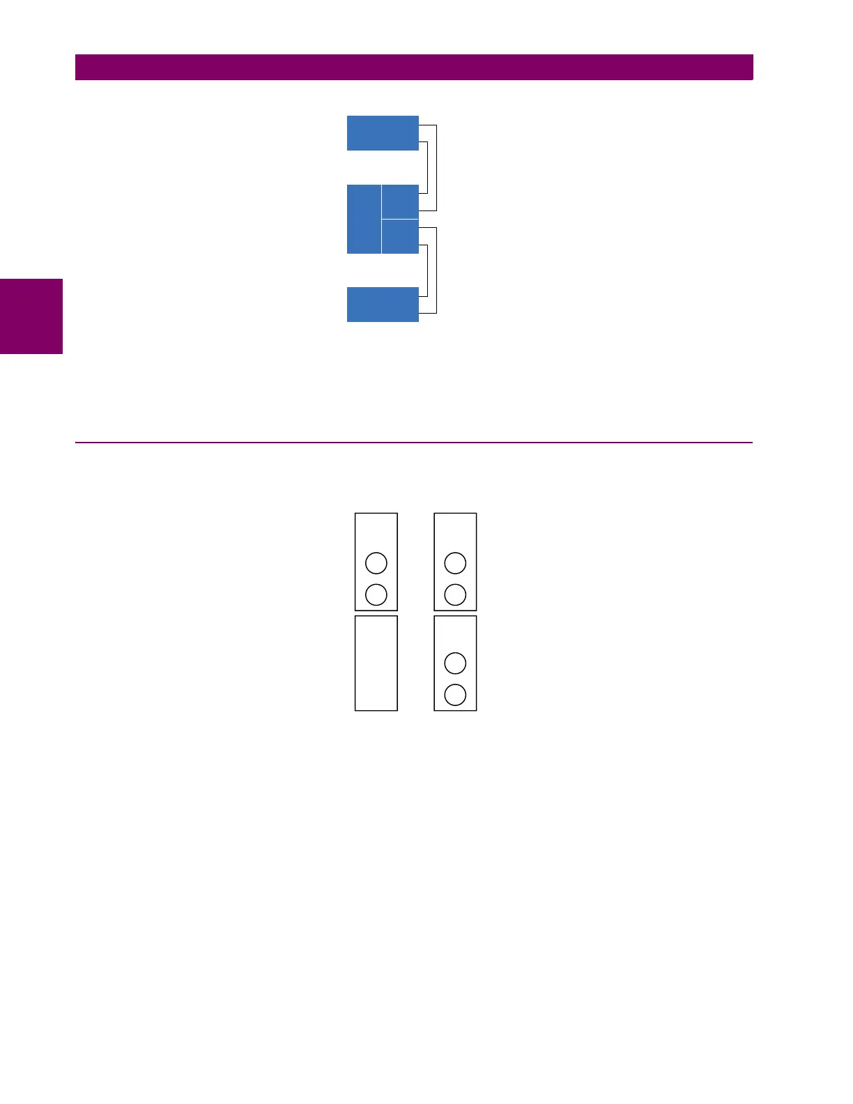
3.3.2 FIBER: LED AND ELED TRANSMITTERS
The following figure shows the configuration for the 7A, 7B, 7C, 7H, 7I, and 7J fiber-only modules.
Figure 3–29: LED AND ELED FIBER MODULES
842013A2.CDR
Channel 1
Channel 2
Tx1
UR 2
Tx2
Rx1
Rx2
Tx
UR 1
Rx
Tx
UR 3
Rx
7A, 7B, and
7C modules
7H, 7I, and
7J modules
1 channel 2 channels
Rx1
Rx1
Rx2
Tx1 Tx1
Tx2
831719A3.CDR
 Loading...


