Home
GE
Relays
T60
GE T60 User Manual
5
of 1
of 1 rating
770 pages
Give review
Manual
Specs
To Next Page
To Next Page
To Previous Page
To Previous Page
Loading...
5-130
T60 Transformer Protection System
GE Multilin
5.4 SYSTEM SETUP
5 SETTINGS
5
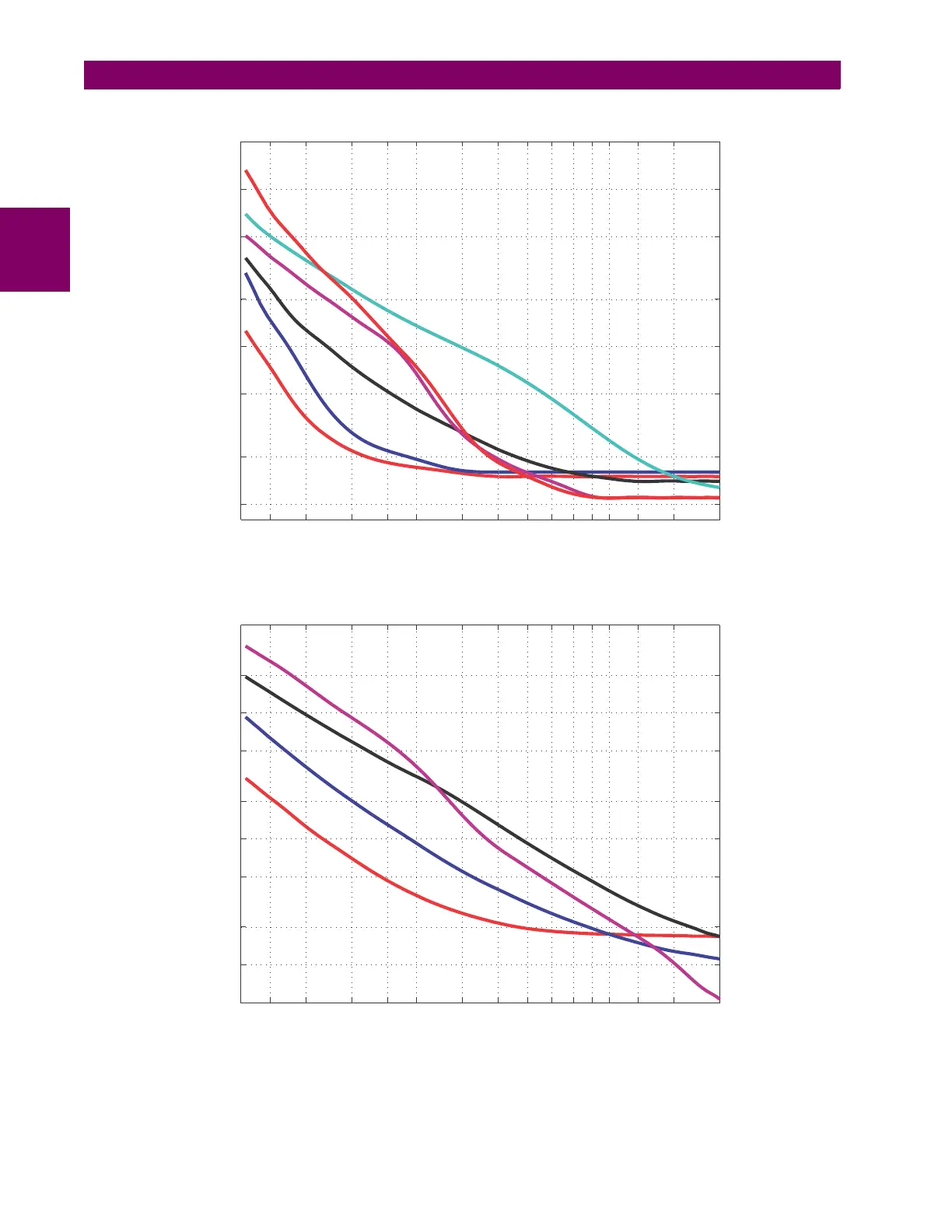
Figure 5–37: RECLOSER
CURVES GE101 TO GE106
Figure 5–38: RECLOSER CURVES
GE1
13, GE120, GE138 AND GE142
GE104
1
1.2
1.5
2
2.5
3
4
5
6
7
8
9
10
12
15
20
0.01
0.02
0.05
0.1
0.2
0.5
1
2
CURRENT (multiple of pic
kup)
TIME (sec)
GE101
GE102
GE103
GE106
GE105
842723A1.CDR
1
1.2
1.5
2
2.5
3
4
5
6
7
8
9
10
12
15
20
0.05
0.1
0.2
0.5
1
2
5
10
20
50
CURRENT (multiple of pic
kup)
TIME (sec)
GE113
GE142
GE138
GE120
842725A1.CDR
263
265
Table of Contents
Default Chapter
3
Table of Contents
3
1 Getting Started
11
Important Procedures
11
Cautions and Warnings
11
Inspection Procedure
12
Rear Nameplate (Example)
12
Ur Overview
13
Introduction to the Ur
13
Hardware Architecture
13
Ur Basic Design
13
Software Architecture
14
Enervista Ur Setup Software
15
System Requirements
15
Installation
15
Adding a Ur Device in Launchpad Window
15
Configuring the T60 for Software Access
16
Ur Device Added to Launchpad Window
16
Configuring Serial Communications
17
Configuring Ethernet Communications
18
Using the Quick Connect Feature
19
Ethernet Cross-Over Cable Pin Layout
19
Using Quick Connect Via the Rear Ethernet Ports
19
Connecting to the T60 Relay
24
Quick Action Hot Links
24
Setting up Cybersentry and Changing Default Password
25
Login Screen for Cybersentry
25
Changing the Default Password
26
Ur Hardware
27
Mounting and Wiring
27
Communications
27
Faceplate Display
27
Using the Relay
28
Faceplate Keypad
28
Menu Navigation
28
Menu Hierarchy
28
Relay Activation
29
Relay Passwords
29
Flexlogic Customization
29
Commissioning
30
Out-Of-Service Maintenance
30
Ansi Device Numbers and Functions
31
2 Product Description
31
Introduction
31
Overview
31
Single Line Diagram
33
Enervista Security
34
Other Device Functions
34
Password Security
34
Cybersentry Security
35
Cybersentry User Roles
35
Permissions by User Role for Cybersentry
36
Cybersentry Server Authentication
38
Iec 870-5-103 Protocol
38
Order Codes with Enhanced Ct/Vt Modules
39
Overview
39
T60 Order Codes (Horizontal Units)
40
T60 Order Codes (Reduced Size Vertical Units)
41
T60 Order Codes (Horizontal Units with Process Bus)
43
Replacement Modules
48
Order Codes for Replacement Modules, Horizontal Units
48
Order Codes for Replacement Modules, Vertical Units
49
Specifications
50
Protection Elements
50
User-Programmable Elements
54
Monitoring
55
Metering
56
Inputs
57
Power Supply
58
Outputs
58
Control Power External Output
59
Fast Form-C Relay
59
Solid-State Output Relay
59
Communication Protocols
60
Inter-Relay Communications
60
Shielded Twisted-Pair Interface Options
60
Environmental
61
Ambient Temperatures
61
Typical Link Distance
61
Type Tests
62
Production Tests
62
Approvals
63
Maintenance
63
Cleaning
63
Mounting
63
3 Hardware
65
Panel Cutout
65
Horizontal Units
65
T60 Horizontal Dimensions (Enhanced Panel)
65
Description
65
T60 Horizontal Mounting (Enhanced Panel)
66
T60 Horizontal Mounting and Dimensions (Standard Panel)
66
Vertical Units
66
T60 Vertical Dimensions (Enhanced Panel)
67
T60 Vertical Mounting and Dimensions (Standard Panel)
68
T60 Vertical Side Mounting Installation (Standard Panel)
69
T60 Vertical Side Mounting Rear Dimensions (Standard Panel)
70
Example of Modules in F and H Slots
71
Rear Terminal View
71
Typical Wiring
72
Typical Wiring Diagram (T Module Shown for Cpu)
72
Control Power
73
Dielectric Strength of Ur-Series Module Hardware
73
Control Power Connection
74
Ct/Vt Modules
74
Ct/Vt Module Wiring
75
Zero-Sequence Core Balance Ct Installation
75
Contact Inputs and Outputs
76
Process Bus Modules
76
Use of Form-A and Solid-State Relay Outputs in High Impedance Circuits
77
Contact Input and Output Module Assignments
78
Contact Input and Output Module Wiring
80
Contact Inputs
82
Dry and Wet Contact Input Connections
82
Auto-Burnish Dip Switches
83
Current through Contact Inputs with Auto-Burnishing
83
Use of Contact Inputs with Auto-Burnishing
83
Transducer Input/Output Module Wiring
84
Transducer Inputs/Outputs
84
Rs232 Faceplate Port
85
Rs232 Faceplate Port Connection
85
Rtd Connection
85
Cpu Communication Ports
86
Cpu Module Communications Wiring
86
Rs485 Ports
86
100Base-Fx Fiber Optic Ports
87
Rs485 Serial Connection
87
Irig-B
88
Options for the Irig-B Connection
88
Direct Input/Output Communications
89
Description
89
Direct Input and Output Dual Channel Connection
89
Direct Input and Output Single Channel Connection
89
Direct Input and Output Single/Dual Channel Combination Connection
90
Fiber: Led and Eled Transmitters
90
Led and Eled Fiber Modules
90
2I and 2J Laser Fiber Module
91
7X Laser Fiber Modules
91
Fiber-Laser Transmitters
91
Interface
91
G.703 Interface Configuration
92
G.703 Selection Switch Procedures
92
Typical Pin Interconnection between Two G.703 Interfaces
92
G.703 Octet Timing
93
G.703 Timing Modes
93
G.703 Timing Selection Switch Setting
93
G.703 Timing Selections
93
G.703 Dual Loopback Mode
94
G.703 Minimum Remote Loopback Mode
94
G.703 Test Modes
94
Rs422 Interface
95
Rs422 Interface Connections
95
Two-Channel Application Via Multiplexers
95
Typical Pin Interconnection between Two Rs422 Interfaces
95
Clock and Data Transitions
96
Timing Configuration for Rs422 Two-Channel, Three-Terminal Application
96
Transmit Timing
96
G.703 and Fiber Interface
97
Rs422 and Fiber Interface
97
Rs422 and Fiber Interface Connection
97
G.703 and Fiber Interface Connection
98
Ieee C37.94 Interface
98
Ieee C37.94 Timing Selection Switch Setting
100
Status Leds
100
C37.94Sm Interface
101
C37.94Sm Timing Selection Switch Setting
103
Creating a Site List
105
Engaging a Device
105
Using Settings Files
105
4 Human Interfaces
105
Enervista Ur Setup Software Interface
105
Introduction
105
Enervista Ur Setup Overview
105
Creating and Editing Flexlogic
106
File Support
106
Viewing Actual Values
106
Viewing Triggered Events
106
Enervista Ur Setup Main Window
107
Settings Templates
108
Extended Enervista Ur Setup Features
108
Adding Password Protection to a Template
109
Settings Template View, All Settings Specified as Locked
109
Settings Template View, Two Settings Specified as Editable
109
Applying Templates Via the View in Template Mode Command
110
Viewing the Settings Template
110
Applying Templates Via the View All Settings Command
111
Applying Templates Via the View in Template Mode Settings Command
111
Removing the Settings Template
111
Locking Flexlogic Entries in Edit Mode
112
Locking Flexlogic Equation Entries
112
Securing and Locking Flexlogic Equations
112
Locking Flexlogic Entries through Setting Templates
113
Locking Flexlogic Equations to a Serial Number
113
Secured Flexlogic in Graphical View
113
Settings File Traceability
114
Settings File Traceability Mechanism
114
Typical Settings File Properties Window
114
Device Definition Showing Traceability Data
115
Settings File Report Showing Traceability Data
115
Settings File Traceability Information
115
Additional Traceability Rules
116
Online Device Traceability Information
116
Traceability Data in Actual Values Window
116
Enhanced Faceplate
117
Standard Faceplate
117
Ur-Series Standard Horizontal Faceplate Panels
117
Faceplate Interface
117
Led Indicators
118
Typical Led Indicator Panel for Enhanced Faceplate
118
Ur-Series Standard Vertical Faceplate Panels
118
Event Cause Indicators
120
Status Indicators
120
User-Programmable Indicators
120
Custom Labeling of Leds
121
Default Labels for Led Panel 2
121
Led Panel 2 (Default Labels)
121
Led Panels 2 and 3 (Index Template)
121
Front Panel Report Window
122
Display
127
Keypad
127
Breaker Control
128
Control Mode Selection and Monitoring
128
Control of Two Breakers
128
Faceplate (User Key) Control
128
Menus
129
Control of One Breaker
129
Navigation
129
Example Menu Navigation
130
Hierarchy
130
Highest Level
130
Changing Settings
131
Entering Alphanumeric Text
131
Entering Enumeration Data
131
Entering Numerical Data
131
Activating the Relay
132
Entering Initial Passwords
132
5 Settings
132
Changing Existing Password
133
Invalid Password Entry
133
Overview
135
Introduction to Elements
138
Introduction to Ac Sources
139
Breaker-And-A-Half Scheme
140
Ct/Vt Module Configuration
140
Ct/Vt Input Channel Configuration
141
Security
142
Lost Password
142
Password Requirements
142
Security Overview
142
Settings Menu
135
Product Setup
142
Local Passwords
143
Access Supervision
144
Remote Passwords
144
Dual Permission Security Access
145
Local Setting Auth
145
Password Lockout Duration
145
Access Auth Timeout
146
Enabling the Security Management System
146
Adding a New User
147
To Add User Accounts
147
Access Rights Summary
148
Modifying User Privileges
148
Cybersentry Security Panel
150
Cybersentry Settings through Enervista
150
RADIUS Server Settings
151
Supervisory Panel
151
General Security Settings
152
Cybersentry Settings through the Front Panel
153
Security Alarm Settings
153
Restore Defaults
154
Session Settings
154
Bypass Access
155
Device Authentication
155
Lock Relay
155
Supervisory
155
Failed Authenticate
156
Firmware Lock
156
Serial Inactivity Timeout
156
Supervisor Role
156
Event Number — Event Identification Number (Index)
157
Syslog Format
157
To Configure Server Authentication
157
Activity Value — 16 Bit Unsigned
158
Display Properties
158
Current Cut-Off Level
159
Default Message Intensity
159
Screen Saver Feature
159
Screen Saver Wait Time
159
Clear Relay Records
160
Communications
161
Main Menu
161
Serial Ports
161
Ethernet Network Topology
162
Network Configuration for Single Lan
163
Multiple LANS, no Redundancy
164
Multiple LANS, with Redundancy
164
Network
165
Far-End Fault Indication (Fefi)
166
Parallel Redundancy Protocol (Prp)
166
Example of Parallel Redundant Network
167
Routing
167
Adding and Deleting Static Routes
168
General Conditions to be Satisfied by Static Routes
168
Routing Behavior Compared to Previous Releases
169
Using Static Routes
169
Ip Arp Information
170
Modbus Protocol
170
Routing Table Information
170
Show Routes and Arp Tables
170
Port and Protocol Combinations
171
Protocol
171
Dnp Protocol
172
Dnp / Iec 60870-5-104 Point Lists
175
Iec 61850 Protocol
176
Goose Retransmission Schemes
180
Tftp Protocol
191
Web Server Http Protocol
191
Iec 60870-5-104 Protocol
192
Egd Protocol
193
Iec 60870-5-103 Protocol
195
Commands Mapping Table
199
Modbus User Map
200
Real Time Clock
200
Precision Time Protocol (1588)
201
Ptp Domain Number
202
Ptp Vlan ID
202
Ptp Vlan Priority
202
Strict Power Profile
202
Path Delay Adder
203
Path Delay Asymmetry
203
Sntp Protocol
203
Local Time
204
User-Programmable Fault Report
205
Oscillography
206
Oscillography Cycles/Record Example
206
Analog Channels
207
Digital Channels
207
Data Logger
208
Data Logger Chnl
209
Data Logger Mode
209
Data Logger Storage Capacity Example
209
Data Logger Trigger
209
Block Interval
210
Demand
210
Thermal Demand Characteristic
210
Thermal Exponential
210
Rolling Demand
211
User-Programmable Leds
211
Led Test Sequence
212
Trip and Alarm Leds
213
User-Programmable Led
213
Recommended Settings for User-Programmable Leds
214
User-Programmable Self Tests
214
Control Pushbuttons
215
Control Pushbuttons (Enhanced Faceplate)
215
Control Pushbuttons (Standard Faceplate)
215
Control Pushbutton Logic
216
User-Programmable Pushbuttons
217
Latched Mode
218
Self-Reset Mode
218
User-Programmable Pushbuttons (Enhanced Faceplate)
218
User-Programmable Pushbuttons (Standard Faceplate)
218
User-Programmable Pushbutton Logic
221
Flex State Parameters
223
User-Definable Displays
223
User Display
224
Direct Inputs and Outputs
226
Direct Input and Output Data Rates
227
Extending the Input/Output Capabilities of a Ur-Series Relay
228
Input and Output Extension Via Direct Inputs and Outputs
228
Interlocking Busbar Protection
228
Sample Interlocking Busbar Protection Scheme
228
Interlocking Bus Protection Scheme Via Direct Inputs/Outputs
229
Pilot-Aided Schemes
230
Single-Channel Open Loop Configuration
230
Three-Terminal Line Application
230
Crc Alarm
231
Dual-Channel Closed Loop (Dual-Ring) Configuration
231
Unreturned Messages Alarm
232
Teleprotection
233
Installation
234
Remote Resources Configuration
235
Remote Resources Configuration Menu
235
System Setup
236
Ac Inputs
236
Current Banks
236
Voltage Banks
237
Power System
238
Signal Sources
239
AC Input Actual Values
239
Disturbance Detectors (Internal)
239
Disturbance Detector Logic Diagram
240
Example Use of Sources
240
Transformer Setup Main Menu
241
General Transformer Settings
242
No Load Loss
243
Rated Winding Temp Rise
243
Thermal Capacity
243
Type of Cooling
243
Example Delta-Wye Connected Power Transformer Data
244
Example Transformer
245
Phase Relationships of Three-Phase Transformers
245
Magnitude Compensation
246
Phasors for Abc Sequence
246
Phasors for Acb Sequence
246
Phase and Zero-Sequence Compensation
248
Magnitude, Phase Angle, and Zero Sequence Compensation
250
Differential and Restraint Current Calculations
251
Setup Method a (Preferred)
251
Transformer Windings between Two Breakers
251
Setup Method B (Alternate)
252
Ambient Temperature
253
Top Oil Temperature
253
Transformer Thermal Inputs
253
Winding Currents
253
Breakers
254
Dual Breaker Control Scheme Logic
256
Disconnect Switches
258
Disconnect Switch Scheme Logic
260
Flexcurves
261
Flexcurve Table
261
Settings
261
Flexcurve Configuration with Enervista Ur Setup
262
Recloser Curve Editing
262
Recloser Curve Initialization
262
Composite Recloser Curve with Hct Disabled
263
Composite Recloser Curve with Hct Enabled
263
Standard Recloser Curves
263
Recloser Curves Ge101 to Ge106
264
Recloser Curves Ge113, Ge120, Ge138 and Ge142
264
Recloser Curves Ge131, Ge141, Ge152, and Ge200
265
Recloser Curves Ge134, Ge137, Ge140, Ge151 and Ge201
265
Recloser Curves Ge116, Ge117, Ge118, Ge132, Ge136, and Ge139
266
Recloser Curves Ge133, Ge161, Ge162, Ge163, Ge164 and Ge165
266
Recloser Curves Ge107, Ge111, Ge112, Ge114, Ge115, Ge121, and Ge122
267
Recloser Curves Ge119, Ge135, and Ge202
267
Phasor Measurement Unit
268
Complete Synchrophasor Implementation
268
UR Implementation of IEC 61850-90-5
268
Implementation by Model Number
269
Logical Nodes Supported in each Logical Device
269
N60 Example for Four Logical Device Pmus
269
Data Set Created from User Selected Internal Items
271
Example of Aggregator Data Sets
271
Example: the Creation of Different Data Sets
271
Cfg-2 Based Configuration Solution
272
Configuration Example: Cfg-2 Based Configuration
272
Modification of Sync Word in Cfg-2 for Tr 90-5 Data Sets
272
Basic Configuration
273
Iec 61850–90–5 Pmu 1 Configuration
276
Pmu Calibration
277
Pmu Triggering Overview
278
Frequency Triggering
279
Stat Bits Logic
279
User Triggering
279
Frequency Trigger Scheme Logic
280
Voltage Triggering
280
Current Triggering
281
Voltage Trigger Scheme Logic
281
Current Trigger Scheme Logic
282
Power Triggering
282
Df/Dt Triggering
283
Power Trigger Scheme Logic
283
Rate of Change of Frequency Trigger Scheme Logic
285
Aggregators
286
Pmu Recording
286
Flexlogic Operands Supported by Aggregator
287
Control Blocks
288
Logic for Setting Svena Control Bit
289
Introduction to Flexlogic
291
Ur Architecture Overview
291
T60 Flexlogic Operand Types
292
T60 Flexlogic Operands
293
Flexlogic Operators
302
Flexlogic Rules
302
Flexlogic Evaluation
302
Flexlogic Example
303
Example Logic Scheme
303
Logic Example with Virtual Outputs
303
Flexlogic Worksheet
304
Logic for Virtual Output 3
304
Logic for Virtual Output 4
304
Flexlogic Equation for Virtual Output 3
305
Flexlogic Equation for Virtual Output 4
306
Flexlogic Equation Editor
307
Flexlogic Timers
307
Flexelements
308
Flexelement Scheme Logic
309
Flexelement Direction, Pickup, and Hysteresis
310
Flexelement Base Units
311
Flexelement Input Mode Setting
311
Non-Volatile Latches
313
NON-VOLATILE LATCH OPERATION TABLE (N = 1 to 16) and LOGIC
313
Grouped Elements
314
Setting Group
314
Power Swing Detect
314
Overview
314
Distance
314
Common Distance Settings
315
Distance
315
Memory Voltage Logic
316
Phase Distance
316
Directional Mho Distance Characteristic
318
Directional Quadrilateral Phase Distance Characteristic
319
Non-Directional Mho Distance Characteristic
319
Ho Distance Characteristic Sample Shapes
320
Non-Directional Quadrilateral Phase Distance Characteristic
320
Quadrilateral Distance Characteristic Sample Shapes
321
Applications of Ph Dist Xfmr Vol/Cur Connection Settings
322
Phase Distance Zone 1 Op Scheme
324
Phase Distance Zone 2 Op Scheme
324
Phase Distance Scheme Logic
325
Phase Distance Zones 3 and Higher Op Scheme
325
Ground Distance
326
Directional Quadrilateral Ground Distance Characteristic
328
Non-Directional Quadrilateral Ground Distance Characteristic
328
Ground Distance Zone 1 Op Scheme
331
Ground Distance Zone 2 Op Scheme
331
Ground Distance Zones 3 and Higher Op Scheme
332
Ground Distance Zone 1 Scheme Logic
333
Ground Directional Supervision
334
Ground Distance Zones 2 and Higher Scheme Logic
334
Ground Directional Supervision Scheme Logic
335
Effects of Blinders on the Mho Characteristics
338
Power Swing Detect Mho Operating Characteristics
338
Power Swing Detect Quadrilateral Operating Characteristics
339
Power Sw I2 Supv Enab
340
Power Swing Fwd Reach
340
Power Swing Mode
340
Power Swing Supv
340
Power Swing Blk
341
Power Swing Pickup Delay
341
Power Swing Trip Mode
341
Power Swing Detect Scheme Logic
342
Load Encroachment
345
Load Encroachment Characteristic
345
Load Encroachment Angle
346
Load Encroachment Applied to Distance Element
346
Load Encroachment Reach
346
Load Encroachment Scheme Logic
346
Transformer Elements
347
Percent Differential
348
Percent Differential Calculations
349
Percent Differential Break
350
Percent Differential Operating Characteristic
350
Percent Differential Pickup
350
Percent Differential Slope
350
Inrush Inhibit Level
351
Overexcitation Inhibit Level
351
Overexcitation Inhibit Mode
351
Percent Differential Scheme Logic
352
Hottest-Spot Temperature
353
Instantaneous Differential
353
Instantaneous Differential Scheme Logic
353
Aging Factor
354
Transformer Hottest-Spot Temperature Logic
354
Aging Factor Logic
355
Loss of Life
355
Transformer Loss of Life Logic
356
Phase Current
357
Inverse Toc Characteristics
357
Overcurrent Curve Types
357
Ieee Curve Trip Times (in Seconds)
358
Ieee Inverse Time Curve Constants
358
Iec (Bs) Inverse Time Curve Constants
359
Iec Curve Trip Times (in Seconds)
359
Iec Curves
359
Ge Type Iac Inverse Time Curve Constants
360
Iac Curve Trip Times
360
Iac Curves
360
Definite Time Curve
361
I2T CURVES
361
Recloser Curves
361
Phase Time Overcurrent (Ansi 51P, Iec Ptoc)
362
Phase Time Overcurrent 1 Scheme Logic
363
Phase Time Overcurrent Voltage Restraint Characteristic
363
Phase Instantaneous Overcurrent (Ansi 50P, Iec Pioc)
364
Phase Instantaneous Overcurrent 1 Scheme Logic
364
Phase a Directional Polarization
365
Phase Directional Overcurrent (Ansi 67P, Iec Pvcb/Ptoc)
365
Mode of Operation
366
Phase dir 1 Eca
366
Phase dir 1 Signal Source
366
Phase Directional Scheme Logic
367
Neutral Current
368
Neutral Time Overcurrent (Ansi 51N, Iec Ptoc)
369
Neutral Time Overcurrent 1 Scheme Logic
369
Neutral Instantaneous Overcurrent (Ansi 50N, Iec Pioc)
370
Neutral Ioc1 Scheme Logic
370
Neutral Directional Overcurrent (Ansi 67N, Iec Pdef/Ptoc)
371
Quantities for "Calculated 3I0" Configuration
372
Quantities for "Measured Ig" Configuration
372
Neutral Directional Voltage-Polarized Characteristics
373
Neutral dir Oc1 Fwd Eca
374
Neutral dir Oc1 Op Curr
374
Neutral dir Oc1 Pol Volt
374
Neutral dir Oc1 Pos-Seq Restraint
374
Neutral Directional Overcurrent Logic
375
Ground Current
376
Ground Time Overcurrent (Ansi 51G, Iec Ptoc)
377
Ground Instantaneous Overcurrent (Ansi 50G, Iec Pioc)
378
Ground Toc1 Scheme Logic
378
Restricted Ground Fault
379
Rgf and Percent Differential Zones of Protection
380
Typical Applications of Rgf Protection
380
External High-Current Slg Fault
382
External High-Current Three-Phase Symmetrical Fault
382
External Single-Line-To-Ground Fault
382
Restricted Ground Fault Scheme Logic
382
Breaker Failure
383
Determination of a Breaker Failure Condition
385
Initiation Stage
385
Output
385
Breaker Failure Main Path Sequence
386
Breaker Failure Overcurrent Supervision Reset Time
386
Main Path Sequence
386
Single-Pole Breaker Failure, Initiate
389
Single-Pole Breaker Failure, Timers
389
Three-Pole Breaker Failure, Initiate
390
Three-Pole Breaker Failure, Timers
391
Voltage Elements
392
Inverse Time Undervoltage Curves
393
Phase Undervoltage (Ansi 27P, Iec Ptuv)
394
Phase Undervoltage1 Scheme Logic
394
Phase Overvoltage (Ansi 59P, Iec Ptov)
395
Phase Overvoltage Scheme Logic
395
Neutral Overvoltage (Ansi 59N, Iec Ptov)
396
Neutral Overvoltage1 Scheme Logic
396
Auxiliary Undervoltage (Ansi 27X, Iec Ptuv)
397
Auxiliary Undervoltage Scheme Logic
397
Auxiliary Overvoltage (Ansi 59X, Iec Ptov)
398
Auxiliary Overvoltage Scheme Logic
398
Volts Per Hertz (Ansi 24, Iec Pvph)
399
Volts Per Hertz Scheme Logic
400
Volts-Per-Hertz Curves, Inverse Curve
401
Control Elements
403
Overview
403
Trip Bus 1
403
Trip Bus Fields in the Protection Summary
404
Setting Groups
405
Active Setting Group
406
Selector Switch
407
Selector 1 Full Range
408
Selector 1 Step-Up
408
Selector 1 Step-Up Mode
408
Selector 1 Time-Out
408
Time-Out Mode
410
Acknowledge Mode
411
Application Example
411
Selector Switch Logic
412
Underfrequency
413
Underfrequency Scheme Logic
413
Overfrequency
414
Overfrequency Scheme Logic
414
Frequency Rate of Change
415
Freq Rate 1 Max Frequency
416
Freq Rate 1 Min Frequency
416
Frequency Rate of Change Scheme Logic
416
Synchrocheck
417
Notes on the Synchrocheck Function
419
Synchrocheck Scheme Logic
420
Digital Elements
421
Digital Element Scheme Logic
421
Breaker Trip Circuit Integrity Monitoring
422
Circuit Monitoring Applications
422
Trip Circuit Example
422
Digital Counters
424
Digital Counter Scheme Logic
425
Monitoring Elements
426
Breaker Arcing Current
427
Arcing Current Measurement
428
Breaker Arcing Current Scheme Logic
429
Breaker Flashover
430
Six Vt Breaker Flashover Application
431
Three Vt Breaker Flashover Application
431
Breaker Flashover Scheme Logic
434
Breaker Restrike
435
Typical Restrike Waveform and Detection Flag
435
Algorithm Illustration – State Machine to Detect Restrike
436
Breaker Restrike Scheme Logic
437
Ct Failure Detector
437
Ct Failure Detector Scheme Logic
438
Vt Fuse Failure
439
Vt Fuse Fail Scheme Logic
440
Thermal Overload Protection
441
Iec 255-8 Sample Operate and Reset Curves
442
Thermal Overload Protection Scheme Logic
443
Typical Time Constants
443
Inputs and Outputs
444
Contact Inputs
444
Input Contact Debouncing Mechanism and Time-Stamping Sample Timing
445
Virtual Inputs
446
Virtual Inputs Scheme Logic
446
Contact Outputs
447
Digital Outputs
447
Latching Outputs
447
Virtual Outputs
449
Remote Devices
450
Local Devices: ID of Device for Transmitting Gsse Messages
450
Remote Inputs/Outputs Overview
450
Remote Devices: ID of Device for Receiving Gsse/Goose Messages
451
Remote Inputs
451
Remote Double-Point Status Inputs
452
Dna Bit Pairs
452
Remote Outputs
452
Users Bit Pairs
453
Resetting
453
Iec 61850 Dna Assignments
453
Remote Outputs
453
Application Examples
454
Direct Inputs and Outputs
454
Extending Input/Output Capabilities of a T60 Relay
455
Single-Channel Open-Loop Configuration
456
Teleprotection Inputs and Outputs
457
Signal Flow for Direct Input and Output
457
Teleprotection Outputs
458
Teleprotection Input/Output Processing
459
Iec 61850 Goose Analogs
459
Goose Analog Input Base Units
460
Iec 61850 Goose Integers
460
Dcma Inputs
462
Transducer Inputs and Outputs
462
Rtd Inputs
463
Rtd Temperature Vs. Resistance
464
Rrtd Inputs
464
Dcma Outputs
468
Remote Rtd Input Protection Logic
468
Dcma Output Characteristic
469
Example: Power Monitoring
469
Example: Current Monitoring
470
Example: Voltage Monitoring
470
Testing
472
Test Mode
472
Force Contact Inputs
473
Test Mode Operation
473
Force Contact Outputs
474
Phasor Measurement Unit Test Values
475
Actual Values Menu
477
Overview
477
Contact Inputs
480
Virtual Inputs
480
Remote Inputs
480
Teleprotection Inputs
481
Contact Outputs
481
Virtual Outputs
482
Remote Devices
482
Digital Counters
483
Selector Switches
483
Flex States
483
Ethernet
483
Real Time Clock Synchronizing
484
Direct Inputs
485
Direct Devices Status
485
Iec 61850 Goose Integers
486
Egd Protocol Status
486
Teleprotection Channel Tests
487
Remaining Connection Status
487
Parallel Redundancy Protocol (Prp)
488
Metering Conventions
489
Flow Direction of Signed Values for Watts and Vars
489
Power and Energy
489
Phase Angles
490
Symmetrical Components
490
Ur Phase Angle Measurement Convention
490
Wye-Connected Instrument Transformers
490
Delta-Connected Instrument Transformers
491
Measurement Convention for Symmetrical Components
491
Symmetrical Components Calculation Example
491
Transformer
492
Differential and Restraint Currents
492
Thermal Elements
492
Sources
493
Phase Current Metering
493
Ground Current Metering
494
Phase Voltage Metering
494
Auxiliary Voltage Metering
495
Power Metering
495
Demand Metering
496
Energy Metering
496
Frequency Metering
497
Current Harmonics and Thd Metering
498
Tracking Frequency
498
Synchrocheck
498
Frequency Rate of Change
499
Flexelements
499
Iec 61580 Goose Analog Values
500
Phasor Measurement Unit
500
Pmu Aggregator
501
Volts Per Hertz
501
Restricted Ground Fault
502
Transducer Inputs and Outputs
502
Distance
502
Status
477
Records
504
User-Programmable Fault Reports
504
Event Records
504
Oscillography
504
Data Logger
505
Phasor Measurement Unit Records
505
Breaker Maintenance
506
Product Information
507
Model Information
507
Firmware Revisions
507
7 Commands and
509
Commands
509
Commands Menu
509
Virtual Inputs
509
Clear Records
509
Set Date and Time
509
Relay Maintenance
511
Phasor Measurement Unit One-Shot
512
Security
513
Targets
514
Targets Menu
514
Target Messages
514
Relay Self-Tests
514
Major Self-Test Error Messages
515
Minor Self-Test Error Messages
516
Equipment Mismatch Major Self-Test
519
Hardfiber Self-Test Error Messages
519
Sfp X Module Fail Messages
519
Wrong Transceiver Messages
519
Brick Trouble Minor Self-Test
520
Process Bus Failure Major Self-Test
520
Process Bus Trouble Minor Self-Test
520
Differential Characteristic Test
521
Minimum Pickup
521
8 Commissioning
521
Description
521
Slope 1 / Breakpoint 1
522
Differential Restraint Characteristic
522
Differential Characteristic Test Examples
523
Introduction
523
Operating Criteria
524
Relay Configuration
524
Test Set Configuration
524
Transformer Data
524
Test Example 1
524
Minimum Pickup Test
525
Test for Zero Differential Current
525
Intermediate Curve between Breakpoint 1 and Breakpoint 2
527
Test Example 2
529
Test Example 3
530
Test Example 4
531
Inrush Inhibit Test Procedure
533
Inrush Inhibit Test Summary
533
Overexcitation Inhibit Test Procedure
534
Overexcitation Inhibit Test Summary
534
Testing Underfrequency and Overfrequency Elements
535
Typical Underfrequency Element Test Timing
535
Frequency Element Tests
535
Commissioning Test Tables
537
Differential Restraint Tests
537
Inrush Inhibit Tests
537
Overexcitation Inhibit Tests
538
Replace a Module
539
9 Maintenance
539
Replace Battery
541
Replace Battery for Rh/Rl Power Supply
541
Battery Location on Rh/Rl Power Supply Module
541
Batteries
541
Battery Location on Sh/Sl Power Supply Module
542
Replace Battery for Sh/Sl Power Supply
542
Dispose of Battery
543
Parameter Lists
547
A.1.1 Flexanalog Items
547
A.1.2 Flexinteger Items
571
Flexinteger Items
571
Modbus Communications
573
Modbus Rtu Protocol
573
Physical Layer
573
Data Link Layer
573
Introduction
573
B.1.1 Introduction
573
Modbus Rtu Crc-16 Algorithm
574
Modbus Tcp/Ip Format
574
Modbus Function Codes
576
Supported Function Codes
576
Read Actual Values or Settings (Function Code 03/04H
576
Execute Operation (Function Code 05H)
577
Store Single Setting (Function Code 06H)
577
Summary of Operation Codes for Function 05H
577
Master and Slave Device Packet Transmission Example
577
Store Multiple Settings (Function Code 10H)
578
Exception Responses
578
Other Protocols
579
Comtrade, Oscillography, and Data Logger Files
579
Reading Oscillography Files
579
B.3.1 Obtaining Relay Files Via Modbus
579
Reading Data Logger Files
580
Reading Event Recorder Files
580
File Transfers
580
Memory Mapping
581
Modbus Memory Map
581
Data Formats
655
B.4.2 Data Formats
655
Enumeration: Curve Shapes
656
Enumeration: Reset Type
656
Enumeration: Phase Rotation
656
Enumeration: Off/On
656
Enumeration: Pmu Phasors
672
Enumeration: Pmu Recording/Reporting Rate
672
Enumeration: Pmu Reporting Style
672
Enumeration: Rtd Input Application
672
Iec 61850
693
Overview
693
Introduction
693
C.1.2 Communication Profiles
693
Server Data Organization
694
Ggio1: Digital Status Values
694
Ggio2: Digital Control Values
694
Ggio3: Digital Status and Analog Values from Goose Data
694
Overview
694
Ggio4: Generic Analog Measured Values
694
C.2.1 Overview
694
Mmxu: Analog Measured Values
695
Protection and Other Logical Nodes
695
Server Features and Configuration
697
Buffered/Unbuffered Reporting
697
File Transfer
697
Timestamps and Scanning
697
Logical Device Name
697
Location
697
Logical Node Name Prefixes
698
Connection Timing
698
Non-Iec 61850 Data
698
Communication Software Utilities
698
Generic Substation Event Services: Gsse and Goose
699
Gsse Configuration
699
Fixed Goose
699
Configurable Goose
699
C.4.1 Overview
699
Ethernet Mac Address for Gsse/Goose
702
Gsse ID and Goose ID Settings
702
Iec 61850 Implementation Via Enervista Ur Setup
703
Overview
703
C.5.1 Overview
703
Configuring Iec 61850 Settings
704
About ICD Files
705
Creating an ICD File with Enervista Ur Setup
709
About Scd Files
709
Scd File Structure, Scl (Root) Node
710
Scd File Structure, Substation Node
710
Scd File Structure, Communications Node
711
Importing an Scd File with Enervista Ur Setup
712
Scd File Structure, Ied Node
712
Acsi Conformance
714
Acsi Basic Conformance Statement
714
Acsi Models Conformance Statement
714
Acsi Services Conformance Statement
715
Logical Nodes Table
718
Iec 60870-5-103
723
Overview
723
D.1.2 Factor and Offset Calculation to Transmit Measurand
723
D.1.3 Interoperability Document
724
Iec 60870-5-104 Protocol
729
Interoperability Document
729
E.1.1 Interoperability Document
729
Application Layer
730
Selection of Standard Asdus
730
Process Information in Control Direction
731
System Information in Control Direction
731
Spontaneous Transmission
735
Station Interrogation
735
Command Transmission
735
Point List
737
E.1.2 Point List
737
Device Profile Document
739
Dnp V3.00 Device Profile
739
Requires Application Layer Confirmation
740
F.1.2 Implementation Table
742
Dnp Point Lists
746
Binary Input Points
746
Binary and Control Relay Output
747
F.2.3 Counters
748
F.2.4 Analog Inputs
749
Radius Server Configuration
751
Change Notes
753
H.1.1 Revision History
753
Changes to the T60 Manual
754
Major Updates for T60 Manual Revision Aa1
754
Major Updates for T60 Manual Revision Aa2
754
Major Updates for T60 Manual Revision Y1
755
Major Updates for T60 Manual Revision Y2
755
Major Updates for T60 Manual Revision Y3
755
Major Updates for T60 Manual Revision Z1
755
H.2.1 Standard Abbreviations
758
Warranty
760
Ge Multilin Warranty
760
H.3.1 Ge Multilin Warranty
760
Index
761
5
Based on 1 rating
Ask a question
Give review
Questions and Answers:
Need help?
Do you have a question about the GE T60 and is the answer not in the manual?
Ask a question
GE T60 Specifications
General
Frequency
50/60 Hz
Mounting
Panel Mount
Protection Functions
Overcurrent
Communication Protocols
DNP3
Operating Temperature
+70°C
Enclosure
IP54 (front panel)
Related product manuals
GE T35
610 pages
GE TOV
27 pages
745 TRANSFORMER MANAGEMENT RELAY
408 pages
GE UR T60
724 pages
GE IAC
32 pages
GE B90
510 pages
GE 489
306 pages
GE P642
592 pages
GE P741
560 pages
GE UR series
652 pages
GE IAC Series
36 pages
GE Multilin 489
314 pages

 Loading...


