GE Multilin T60 Transformer Protection System 2-31
2 PRODUCT DESCRIPTION 2.3 SPECIFICATIONS
2
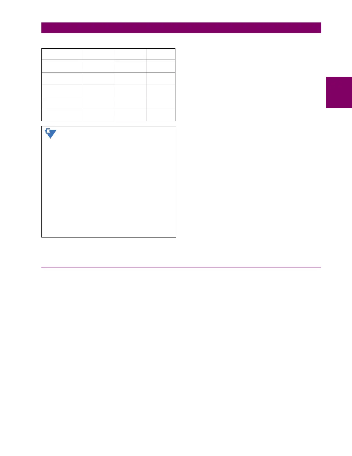
TYPICAL LINK DISTANCE
Compensated difference in transmitting and receiving (channel
asymmetry) channel delays using GPS satellite clock: 10 ms
2.3.10 ENVIRONMENTAL
AMBIENT TEMPERATURES
Storage temperature: –40 to 85°C
Operating temperature: –40 to 60°C; the LCD contrast can be
impaired at temperatures less than –
20°C
HUMIDITY
Humidity: operating up to 95% (non-condensing) at
55°C (as per IEC60068-2-30 variant 1, 6
days).
OTHER
Altitude: 2000 m (maximum)
Pollution degree: II
Overvoltage category: II
Ingress protection: IP20 front, IP10 back
EMITTER TYPE CABLE
TYPE
CONNECTOR
TYPE
TYPICAL
DISTANCE
820 nm LED,
multimode
62.5/125 μmST 1.65 km
1300 nm LED,
multimode
62.5/125 μm ST 3.8 km
1300 nm ELED,
single mode
9/125 μmST11.4 km
1300 nm Laser,
single mode
9/125 μm ST 64 km
1550 nm Laser,
single mode
9/125 μm ST 105 km
Typical distances listed are based on the follow-
ing assumptions for system loss. As actual losses
vary from one installation to another, the distance
covered by your system may vary.
CONNECTOR LOSSES (TOTAL OF BOTH ENDS)
ST connector 2 dB
FIBER LOSSES
820 nm multimode 3 dB/km
1300 nm multimode 1 dB/km
1300 nm single mode 0.35 dB/km
1550 nm single mode 0.25 dB/km
Splice losses: One splice every 2 km,
at 0.05 dB loss per splice.
SYSTEM MARGIN
3 dB additional loss added to calculations to compensate for
all other losses.
 Loading...


