5-182 T60 Transformer Protection System GE Multilin
5.6 GROUPED ELEMENTS 5 SETTINGS
5
The distance zones can be forced to become self-polarized through the FORCE SELF-POLAR setting. Any user-selected con-
dition (FlexLogic operand) can be configured to force self-polarization. When the selected operand is asserted (logic 1), the
distance functions become self-polarized regardless of other memory voltage logic conditions. When the selected operand
is de-asserted (logic 0), the distance functions follow other conditions of the memory voltage logic as shown below.
The distance zones can be forced to become memory-polarized through the FORCE MEM-POLAR setting. Any user-selected
condition (any FlexLogic operand) can be configured to force memory polarization. When the selected operand is asserted
(logic 1), the distance functions become memory-polarized regardless of the positive-sequence voltage magnitude at this
time. When the selected operand is de-asserted (logic 0), the distance functions follow other conditions of the memory volt-
age logic.
The
FORCE SELF-POLAR and FORCE MEM-POLAR settings should never be asserted simultaneously. If this happens, the logic
will give higher priority to forcing self-polarization as indicated in the logic below. This is consistent with the overall philoso-
phy of distance memory polarization.
The memory polarization cannot be applied permanently but for a limited time only; the self-polarization may be
applied permanently and therefore should take higher priority.
In firmware 7.20, when the fast distance algorithm is applied, the HardFiber brick is not supported. The fast dis-
tance algorithm is supported by the T60. It is not supported by the HardFiber, which maintains the original distance
element timing.
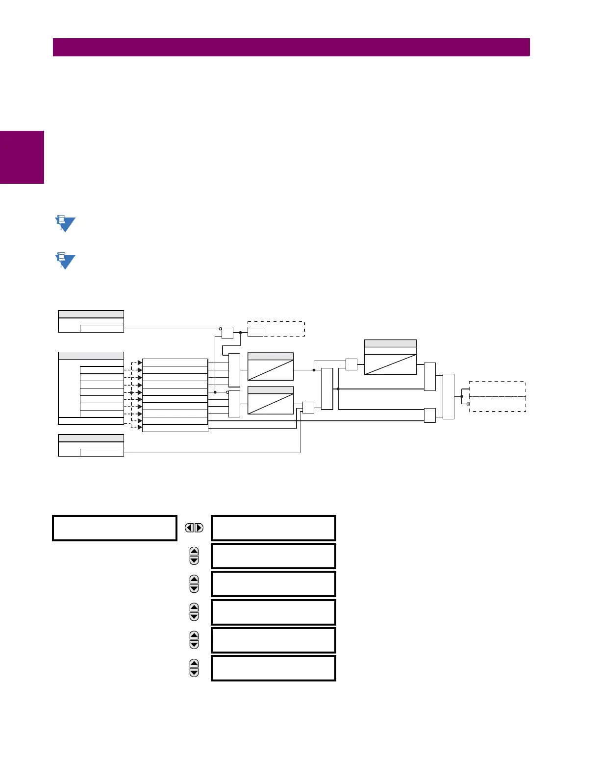
Figure 5–70: MEMORY VOLTAGE LOGIC
b) PHASE DISTANCE
PATH: SETTINGS GROUPED ELEMENTS SETTING GROUP 1(6) DISTANCE PHASE DISTANCE Z1(Z5)
PHASE DISTANCE Z1
PHS DIST Z1
FUNCTION: Disabled
Range: Disabled, Enabled
MESSAGE
PHS DIST Z1 DIR:
Forward
Range: Forward, Reverse, Non-directional
MESSAGE
PHS DIST Z1
SHAPE: Mho
Range: Mho, Quad
MESSAGE
PHS DIST Z1 XFMR VOL
CONNECTION: None
Range: None, Dy1, Dy3, Dy5, Dy7, Dy9, Dy11, Yd1, Yd3,
Yd5, Yd7, Yd9, Yd11
MESSAGE
PHS DIST Z1 XFMR CUR
CONNECTION: None
Range: None, Dy1, Dy3, Dy5, Dy7, Dy9, Dy11, Yd1, Yd3,
Yd5, Yd7, Yd9, Yd11
MESSAGE
PHS DIST Z1
REACH: 2.00 ohms
Range: 0.02 to 500.00 ohms in steps of 0.01
827842A9.CDR
Use V_1
Use V_1 memory
AND
AND
OR
AND
AND
S Q
R
RUN
Update memory
SETTING
Off = 0
Force Memory Polarization
| V_1 | < 1.15 pu
| Vrms – | V | | < Vrms / 8
| Vrms – | V | | < Vrms / 8
| Vrms – | V | | < Vrms / 8
| V_1 | > 0.80 pu
| IA | < 0.05 pu
| IB | < 0.05 pu
SETTING
Off = 0
Force Self Polarization
SETTING
= VA, Vrms_A
= VB, Vrms_B
Distance Source
= VC, Vrms_C
= V_1
= IA
= IB
= IC
| IC | < 0.05 pu
| V_1 | < 0.10 pu
TIMER
5 cycles
0
TIMER
6 cycles
0
AND
AND
OR
SETTING
Memory duration
0
T
reset
Tracking Freq, *SRCx Freq
= IC
| f - f | > 1 Hz
TRACK SRC
*SRCx is the source used in distance
L90 Only

 Loading...


