6-24 T60 Transformer Protection System GE Multilin
6.3 METERING 6 ACTUAL VALUES
6
6.3.8 IEC 61580 GOOSE ANALOG VALUES
PATH: ACTUAL VALUES METERING IEC 61850 GOOSE ANALOGS
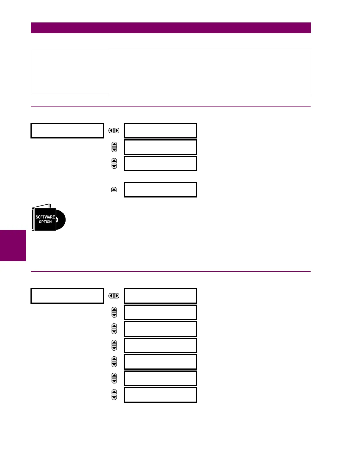
The T60 Transformer Protection System is provided with optional IEC 61850 communications capability.
This feature is specified as a software option at the time of ordering. See the Order Codes section of chap-
ter 2 for details.
The IEC 61850 GGIO3 analog input data points are displayed in this menu. The GGIO3 analog data values are received
via IEC 61850 GOOSE messages sent from other devices.
6.3.9 PHASOR MEASUREMENT UNIT
PATH: ACTUAL VALUES METERING PHASOR MEASUREMENT UNIT PMU 1
Z
BASE
Z
BASE
= PhaseVTSecondary / PhaseCTSecondary, where PhaseVTSecondary and
PhaseCTSecondary are the secondary nominal voltage and the secondary nominal current of the
distance source. In case multiple CT inputs are summed as one source current and mapped as
the distance source, use the PhaseCTSecondary value from the CT with the highest primary
nominal current.
Distance source is specified in setting under
SETTINGS > GROUPED ELEMENTS > SETTING
GROUP 1(6) > DISTANCE.
PhaseVTSecondary and PhaseCTSecondary are specified in setting under
SETTINGS > SYSTEM
SETUP > AC INPUTS
.
IEC 61850
GOOSE ANALOGS
ANALOG INPUT 1
0.000
MESSAGE
ANALOG INPUT 2
0.000
MESSAGE
ANALOG INPUT 3
0.000
MESSAGE
ANALOG INPUT 32
0.000
PMU 1
PMU 1 VA:
0.0000 kV, 0.00°
Range: Va or Vab per VT bank connection
MESSAGE
PMU 1 VB:
0.0000 kV, 0.00°
Range: Va or Vab per VT bank connection
MESSAGE
PMU 1 VC:
0.0000 kV, 0.00°
Range: Va or Vab per VT bank connection
MESSAGE
PMU 1 VX:
0.0000 kV, 0.00°
MESSAGE
PMU 1 V1:
0.0000 kV, 0.00°
MESSAGE
PMU 1 V2:
0.0000 kV, 0.00°
MESSAGE
PMU 1 V0:
0.0000 kV, 0.00°
Range: Substituted with zero if delta-connected VTs.
Table 6–2: FLEXELEMENT BASE UNITS (Sheet 2 of 2)
 Loading...


