GE Multilin T60 Transformer Protection System 6-21
6 ACTUAL VALUES 6.3 METERING
6
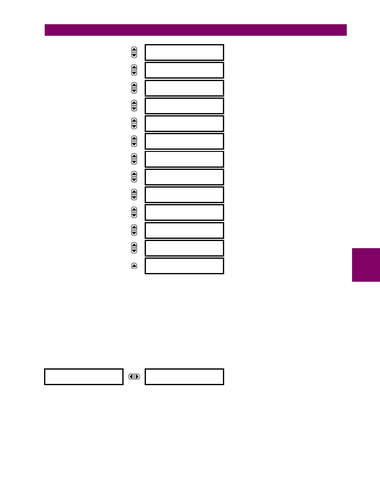
The metered values for current and power demand are displayed in this menu. The "SRC 1" text will be replaced by what-
ever name was programmed by the user for the associated source (see SETTINGS SYSTEM SETUP SIGNAL
SOURCES).
The relay measures (absolute values only) the source demand on each phase and average three phase demand for real,
reactive, and apparent power. These parameters can be monitored to reduce supplier demand penalties or for statistical
metering purposes. Demand calculations are based on the measurement type selected in the
SETTINGS PRODUCT SETUP
DEMAND menu. For each quantity, the relay displays the demand over the most recent demand time interval, the maxi-
mum demand since the last maximum demand reset, and the time and date stamp of this maximum demand value. Maxi-
mum demand quantities can be reset to zero with the
CLEAR RECORDS CLEAR DEMAND RECORDS command.
i) FREQUENCY METERING
PATH: ACTUAL VALUES METERING SOURCE SRC 1 FREQUENCY
The metered frequency values are displayed in this menu. The "SRC 1" text will be replaced by whatever name was pro-
grammed by the user for the associated source (see
SETTINGS SYSTEM SETUP SIGNAL SOURCES).
SOURCE FREQUENCY is measured via software-implemented zero-crossing detection of an AC signal. The signal is either a
Clarke transformation of three-phase voltages or currents, auxiliary voltage, or ground current as per source configuration
(see the
SYSTEM SETUP POWER SYSTEM settings). The signal used for frequency estimation is low-pass filtered. The
final frequency measurement is passed through a validation filter that eliminates false readings due to signal distortions and
transients.
MESSAGE
SRC 1 DMD IB DATE:
2001/07/31 16:30:07
MESSAGE
SRC 1 DMD IC:
0.000 A
MESSAGE
SRC 1 DMD IC MAX:
0.000 A
MESSAGE
SRC 1 DMD IC DATE:
2001/07/31 16:30:07
MESSAGE
SRC 1 DMD W:
0.000 W
MESSAGE
SRC 1 DMD W MAX:
0.000 W
MESSAGE
SRC 1 DMD W DATE:
2001/07/31 16:30:07
MESSAGE
SRC 1 DMD VAR:
0.000 var
MESSAGE
SRC 1 DMD VAR MAX:
0.000 var
MESSAGE
SRC 1 DMD VAR DATE:
2001/07/31 16:30:07
MESSAGE
SRC 1 DMD VA:
0.000 VA
MESSAGE
SRC 1 DMD VA MAX:
0.000 VA
MESSAGE
SRC 1 DMD VA DATE:
2001/07/31 16:30:07
FREQUENCY
SRC 1
SRC 1 FREQUENCY:
0.00 Hz
 Loading...


