GE Multilin T60 Transformer Protection System 6-5
6 ACTUAL VALUES 6.2 STATUS
6
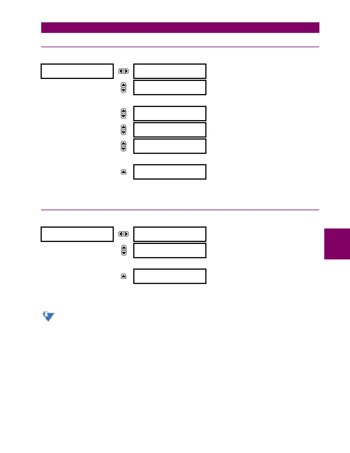
6.2.4 TELEPROTECTION INPUTS
PATH: ACTUAL VALUES STATUS TELEPROTECTION INPUTS
The present state of teleprotection inputs from communication channels 1 and 2 are shown here. The state displayed will
be that of corresponding remote output unless the channel is declared failed.
6.2.5 CONTACT OUTPUTS
PATH: ACTUAL VALUES STATUS CONTACT OUTPUTS
The present state of the contact outputs is shown here. The first line of a message display indicates the ID of the contact
output. For example, ‘Cont Op 1’ refers to the contact output in terms of the default name-array index. The second line of
the display indicates the logic state of the contact output.
For form-A contact outputs, the state of the voltage and current detectors is displayed as Off, VOff, IOff, On, IOn,
and VOn. For form-C contact outputs, the state is displayed as Off or On.
TELEPROTECTION
INPUTS
TELEPROTECTION
INPUT 1-1: Off
Range: Off, On
MESSAGE
TELEPROTECTION
INPUT 1-2: Off
Range: Off, On
MESSAGE
TELEPROTECTION
INPUT 1-16: Off
Range: Off, On
MESSAGE
TELEPROTECTION
INPUT 2-1: Off
Range: Off, On
MESSAGE
TELEPROTECTION
INPUT 2-2: Off
Range: Off, On
MESSAGE
TELEPROTECTION
INPUT 2-16: Off
Range: Off, On
CONTACT OUTPUTS
Cont Op 1
Off
Range: On, Off, VOff, VOn, IOn, IOff
MESSAGE
Cont Op 2
Off
Range: On, Off, VOff, VOn, IOn, IOff
MESSAGE
Cont Op xx
Off
Range: On, Off, VOff, VOn, IOn, IOff

 Loading...


