3-4 T60 Transformer Protection System GE Multilin
3.1 DESCRIPTION 3 HARDWARE
3
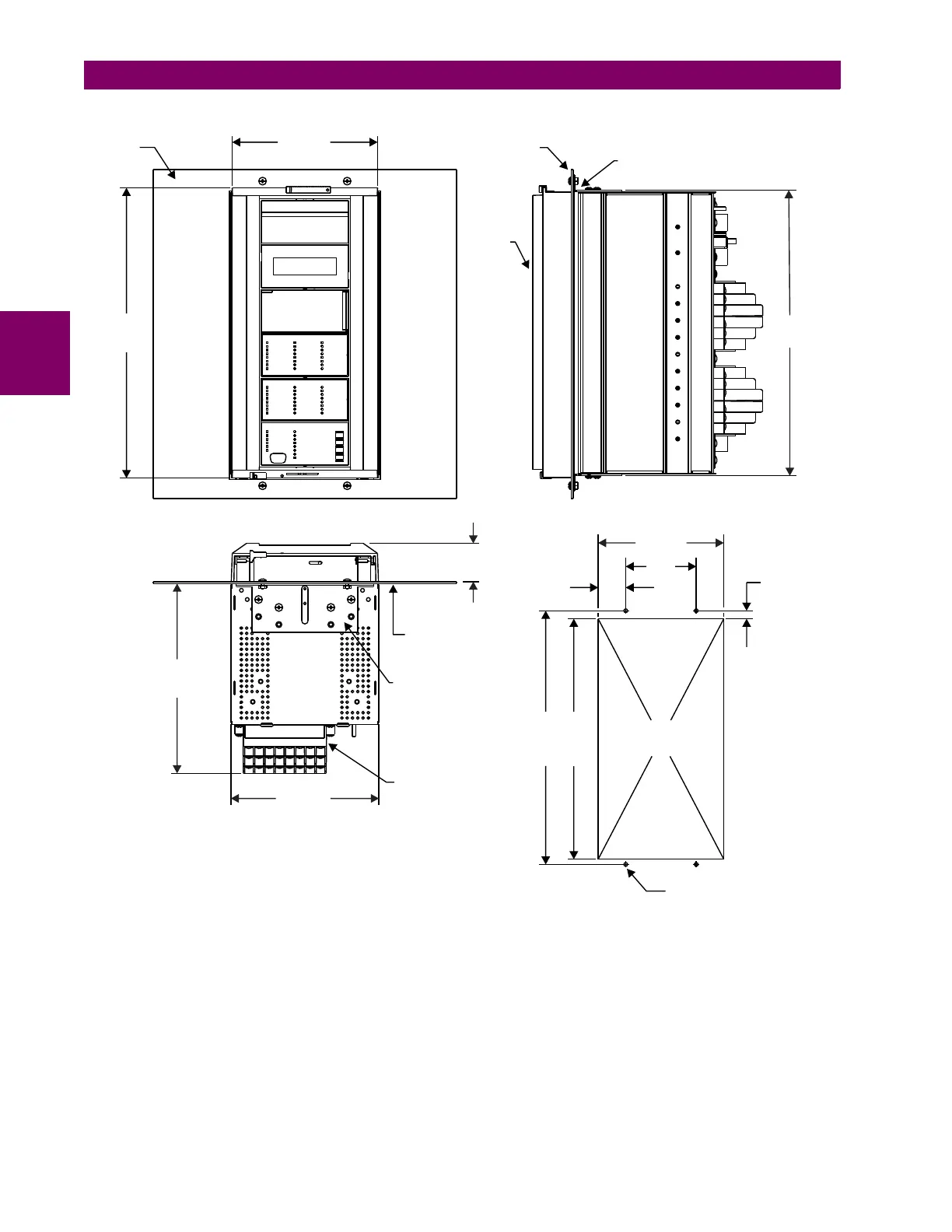
Figure 3–5: T60 VERTICAL MOUNTING AND DIMENSIONS (STANDARD PANEL)
For details on side mounting T60 devices with the enhanced front panel, refer to the following documents available online
from the GE Multilin website.
• GEK-113180: UR-series UR-V side-mounting front panel assembly instructions.
• GEK-113181: Connecting the side-mounted UR-V enhanced front panel to a vertical UR-series device.
• GEK-113182: Connecting the side-mounted UR-V enhanced front panel to a vertically-mounted horizontal UR-series
device.
For details on side mounting T60 devices with the standard front panel, refer to the figures below.
13.72"
(348.5 mm)
7.00"
(177.8 mm)
13.50"
(342.9 mm)
Front of
panel
Front
bezel
Panel
Mounting bracket
1.57”
(39.9 mm)
4.00
(101.6)
7.13”
(181.1 mm)
0.46”
(11.7 mm)
13.65”
(346.7 mm)
14.40”
(365.8 mm)
0.213" (5.4 mm),
4 places
Vertical front view
Vertical side view
843755A4.CDR
Vertical panel mounting
1.85"
(47.0 mm)
9.00"
(228.6 mm)
7.00"
(177.8 mm)
Terminal blocks
Mounting bracket
Panel shown for
reference only
Vertical bottom view
 Loading...


