5-238 T60 Transformer Protection System GE Multilin
5.6 GROUPED ELEMENTS 5 SETTINGS
5
• Transformation errors of current transformers (CTs) during double-line and three-phase faults.
• Switch-off transients during double-line and three-phase faults.
The positive-sequence restraint must be considered when testing for pickup accuracy and response time (multiple of
pickup). The operating quantity depends on the way the test currents are injected into the relay (single-phase injection:
I
op
=(1–K) I
injected
; three-phase pure zero-sequence injection: I
op
= 3 I
injected
).
The positive-sequence restraint is removed for low currents. If the positive-sequence current is below 0.8 pu, the restraint is
removed by changing the constant K to zero. This facilitates better response to high-resistance faults when the unbalance
is very small and there is no danger of excessive CT errors as the current is low.
The directional unit uses the zero-sequence current (I_0) or ground current (IG) for fault direction discrimination and may
be programmed to use either zero-sequence voltage (“Calculated V0” or “Measured VX”), ground current (IG), or both for
polarizing. The zero-sequence current (I_0) must be greater than the
PRODUCT SETUP DISPLAY PROPERTIES CUR-
RENT CUT-OFF LEVEL setting value and IG must be greater than 0.05 pu to be validated as the operating quantity for direc-
tional current. The following tables define the neutral directional overcurrent element.
where: ,
,
ECA = element characteristic angle and IG = ground current
When NEUTRAL DIR OC1 POL VOLT is set to “Measured VX”, one-third of this voltage is used in place of V_0. The following
figure explains the usage of the voltage polarized directional unit of the element.
The figure below shows the voltage-polarized phase angle comparator characteristics for a phase A to ground fault, with:
• ECA = 90° (element characteristic angle = centerline of operating characteristic)
• FWD LA = 80° (forward limit angle = the ± angular limit with the ECA for operation)
• REV LA = 80° (reverse limit angle = the ± angular limit with the ECA for operation)
The above bias should be taken into account when using the neutral directional overcurrent element to directionalize other
protection elements.
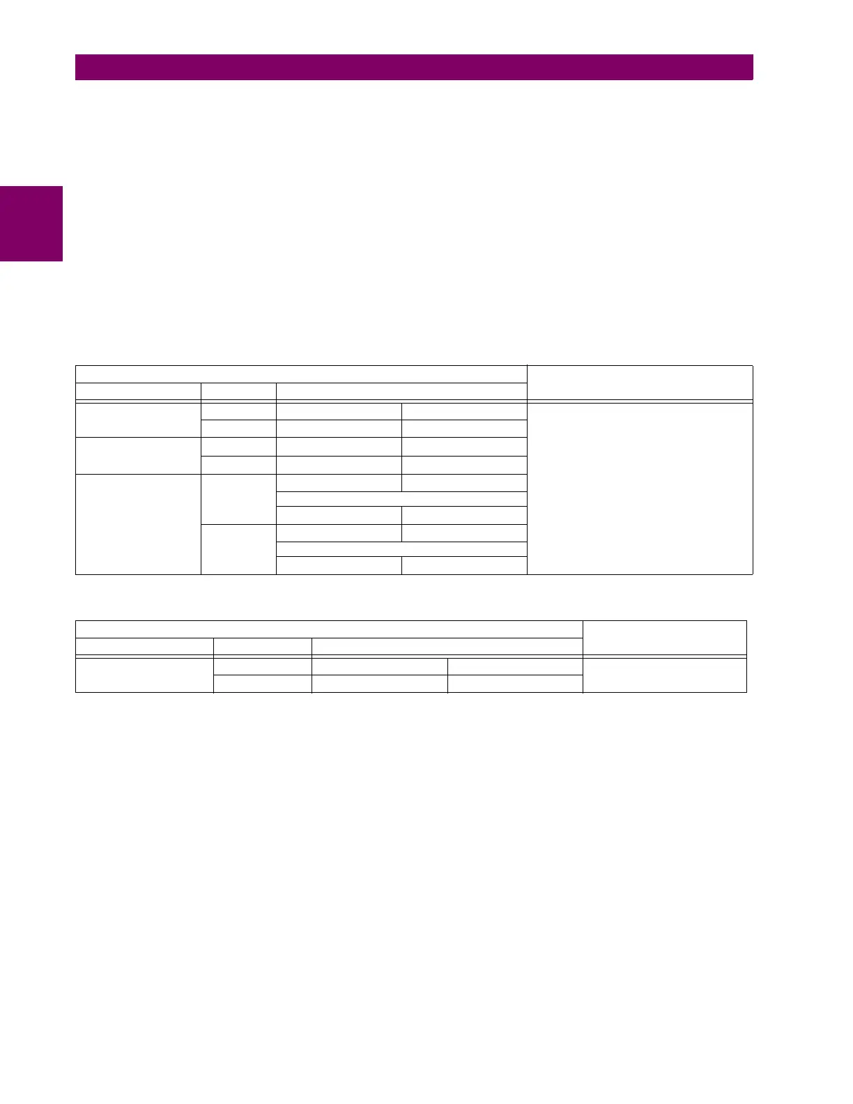
Table 5–31: QUANTITIES FOR "CALCULATED 3I0" CONFIGURATION
DIRECTIONAL UNIT
OVERCURRENT UNIT
POLARIZING MODE DIRECTION COMPARED PHASORS
Voltage
Forward –V_0 + Z_offset I_0 I_0 1ECA
I
op
= 3 (|I_0| – K |I_1|) if |I
1
| > 0.8 pu
I
op
= 3 (|I_0|) if |I
1
| 0.8 pu
Reverse –V_0 + Z_offset I_0 –I_0 1ECA
Current
Forward IG I_0
Reverse IG –I_0
Dual, Dual-V, Dual-I
Forward
–V_0 + Z_offset I_0 I_0 1ECA
or
IG I_0
Reverse
–V_0 + Z_offset I_0 –I_0 1ECA
or
IG –I_0
Table 5–32: QUANTITIES FOR "MEASURED IG" CONFIGURATION
DIRECTIONAL UNIT
OVERCURRENT UNIT
POLARIZING MODE DIRECTION COMPARED PHASORS
Voltage
Forward –V_0 + Z_offset IG/3 IG 1ECA
I
op
= |IG|
Reverse –V_0 + Z_offset IG/3 –IG 1ECA
V_0
1
3
---
VAG VBG VCG++zero sequence voltage==
I_0
1
3
---
IN
1
3
---
IA IB IC++zero sequence current== =
 Loading...


