5-252 T60 Transformer Protection System GE Multilin
5.6 GROUPED ELEMENTS 5 SETTINGS
5
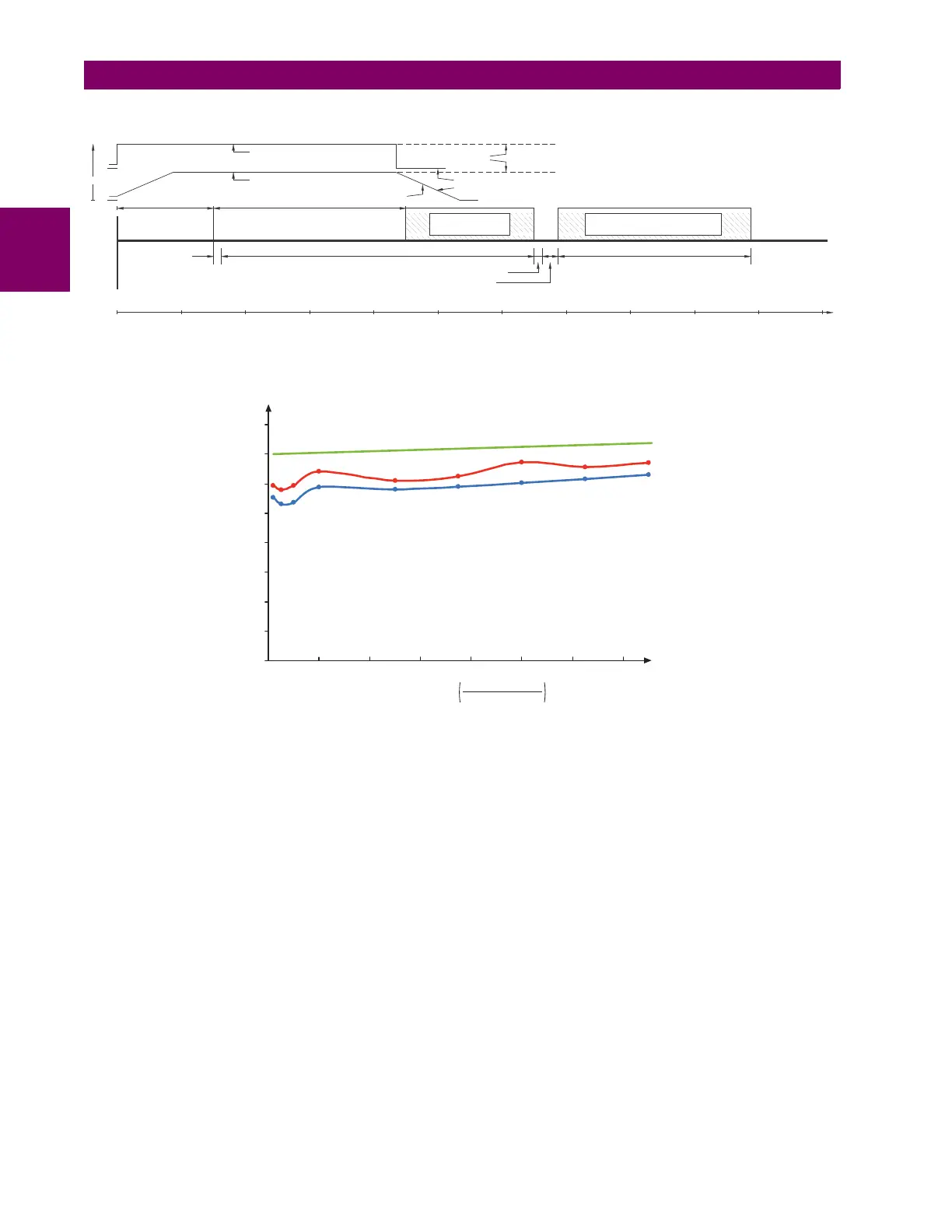
MAIN PATH SEQUENCE:
Figure 5–120: BREAKER FAILURE MAIN PATH SEQUENCE
The current supervision elements reset in less than 0.7 of a power cycle for any multiple of pickup current as shown below.
Figure 5–121: BREAKER FAILURE OVERCURRENT SUPERVISION RESET TIME
SETTINGS:
• BF1 MODE: This setting is used to select the breaker failure operating mode: single or three pole.
• BF1 USE AMP SUPV: If set to "Yes", the element will only be initiated if current flowing through the breaker is above
the supervision pickup level.
• BF1 USE SEAL-IN: If set to "Yes", the element will only be sealed-in if current flowing through the breaker is above the
supervision pickup level.
• BF1 3-POLE INITIATE: This setting selects the FlexLogic operand that will initiate three-pole tripping of the breaker.
• BF1 PH AMP SUPV PICKUP: This setting is used to set the phase current initiation and seal-in supervision level.
Generally this setting should detect the lowest expected fault current on the protected breaker. It can be set as low as
necessary (lower than breaker resistor current or lower than load current) – high-set and low-set current supervision
will guarantee correct operation.
• BF1 N AMP SUPV PICKUP: This setting is used to set the neutral current initiate and seal-in supervision level. Gener-
ally this setting should detect the lowest expected fault current on the protected breaker. Neutral current supervision is
used only in the three phase scheme to provide increased sensitivity. This setting is valid only for three-pole tripping
schemes.
• BF1 USE TIMER 1: If set to "Yes", the early path is operational.
• BF1 TIMER 1 PICKUP DELAY: Timer 1 is set to the shortest time required for breaker auxiliary contact Status-1 to
open, from the time the initial trip signal is applied to the breaker trip circuit, plus a safety margin.
PROTECTION OPERATION BREAKER INTERRUPTING TIME
CALCULATED CURRENT MAGNITUDE
ACTUAL CURRENT MAGNITUDE
FAILED INTERRUPTION
CORRECT INTERRUPTION
Rampdown
(ASSUMED 1.5 cycles)
INITIATE (1/8 cycle)
BREAKER FAILURE TIMER No. 2 (±1/8 cycle)
BREAKER FAILURE CURRENT DETECTOR PICKUP (1/8 cycle)
BREAKER FAILURE OUTPUT RELAY PICKUP (1/4 cycle)
FAULT
OCCURS
12345678910110
0
0
AMP
(ASSUMED 3 cycles)
cycles
827083A6.CDR
MARGIN
(Assumed 2 Cycles)
BACKUP BREAKER OPERATING TIME
(Assumed 3 Cycles)
836769A4.CDR
0
0.2
0.4
0.6
0.8
0 20 40 60 80 100 120 140
Average
Maximum
Margin
MulWLple of pickup
fault current
threshold setting
Breaker failure reset time (cycles)

 Loading...


