GE Multilin T60 Transformer Protection System 6-29
6 ACTUAL VALUES 6.4 RECORDS
6
This menu allows the user to view the number of triggers involved and number of oscillography traces available. The
CYCLES PER RECORD value is calculated to account for the fixed amount of data storage for oscillography. See the Oscillog-
raphy section of chapter 5 for additional details.
A trigger can be forced here at any time by setting “Yes” to the FORCE TRIGGER? command. Refer to the COMMANDS
CLEAR RECORDS menu for information on clearing the oscillography records.
6.4.5 DATA LOGGER
PATH: ACTUAL VALUES RECORDS DATA LOGGER
The OLDEST SAMPLE TIME represents the time at which the oldest available samples were taken. It will be static until the log
gets full, at which time it will start counting at the defined sampling rate. The
NEWEST SAMPLE TIME represents the time the
most recent samples were taken. It counts up at the defined sampling rate. If the data logger channels are defined, then
both values are static.
Refer to the
COMMANDS CLEAR RECORDS menu for clearing data logger records.
6.4.6 PHASOR MEASUREMENT UNIT RECORDS
PATH: ACTUAL VALUES RECORDS PMU RECORDS
The number of triggers applicable to the phasor measurement unit recorder is indicated by the NUMBER OF TRIGGERS value.
The status of the phasor measurement unit recorder is indicated as follows:
PATH: ACTUAL VALUES RECORDS PMU RECORDS PMU 1 RECORDING
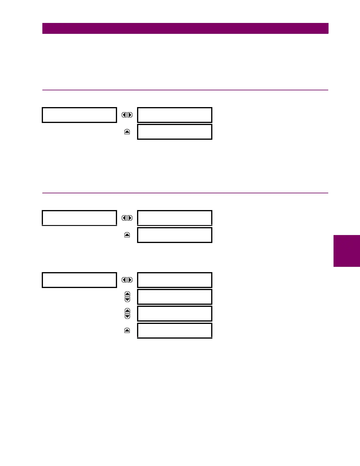
DATA LOGGER
OLDEST SAMPLE TIME:
2000/01/14 13:45:51
MESSAGE
NEWEST SAMPLE TIME:
2000/01/14 15:21:19
PMU
RECORDS
NUMBER OF TRIGGERS:
0
Range: 0 to 65535 in steps of 1
MESSAGE
PMU 1
RECORDING
See below.
PMU 1
RECORDING
PMU 1 FORCE TRIGGER:
Yes
Range: No, Yes
MESSAGE
PUM 1 AVAILABLE
RECORDS: 0
Range: 0 to 65535 in steps of 1
MESSAGE
PUM 1 SECONDS
PER RECORD: 0.0
Range: 0 to 6553.5 in steps of 0.1
MESSAGE
PUM 1 LAST CLEARED:
2013/07/14 15:40:16
Range: date and time in format shown

 Loading...


