GE Multilin T60 Transformer Protection System 3-25
3 HARDWARE 3.3 DIRECT INPUT/OUTPUT COMMUNICATIONS
3
3.3DIRECT INPUT/OUTPUT COMMUNICATIONS 3.3.1 DESCRIPTION
The direct inputs and outputs feature makes use of the type 7 series of communications modules, which allow direct mes-
saging between UR devices. These communications modules are outlined in the table later in this section.
The communications channels are normally connected in a ring configuration as shown in the following figure. The trans-
mitter of one module is connected to the receiver of the next module. The transmitter of this second module is then con-
nected to the receiver of the next module in the ring. This is continued to form a communications ring. The figure illustrates
a ring of four UR-series relays with the following connections: UR1-Tx to UR2-Rx, UR2-Tx to UR3-Rx, UR3-Tx to UR4-Rx,
and UR4-Tx to UR1-Rx. A maximum of 16 UR-series relays can be connected in a single ring
Figure 3–26: DIRECT INPUT AND OUTPUT SINGLE CHANNEL CONNECTION
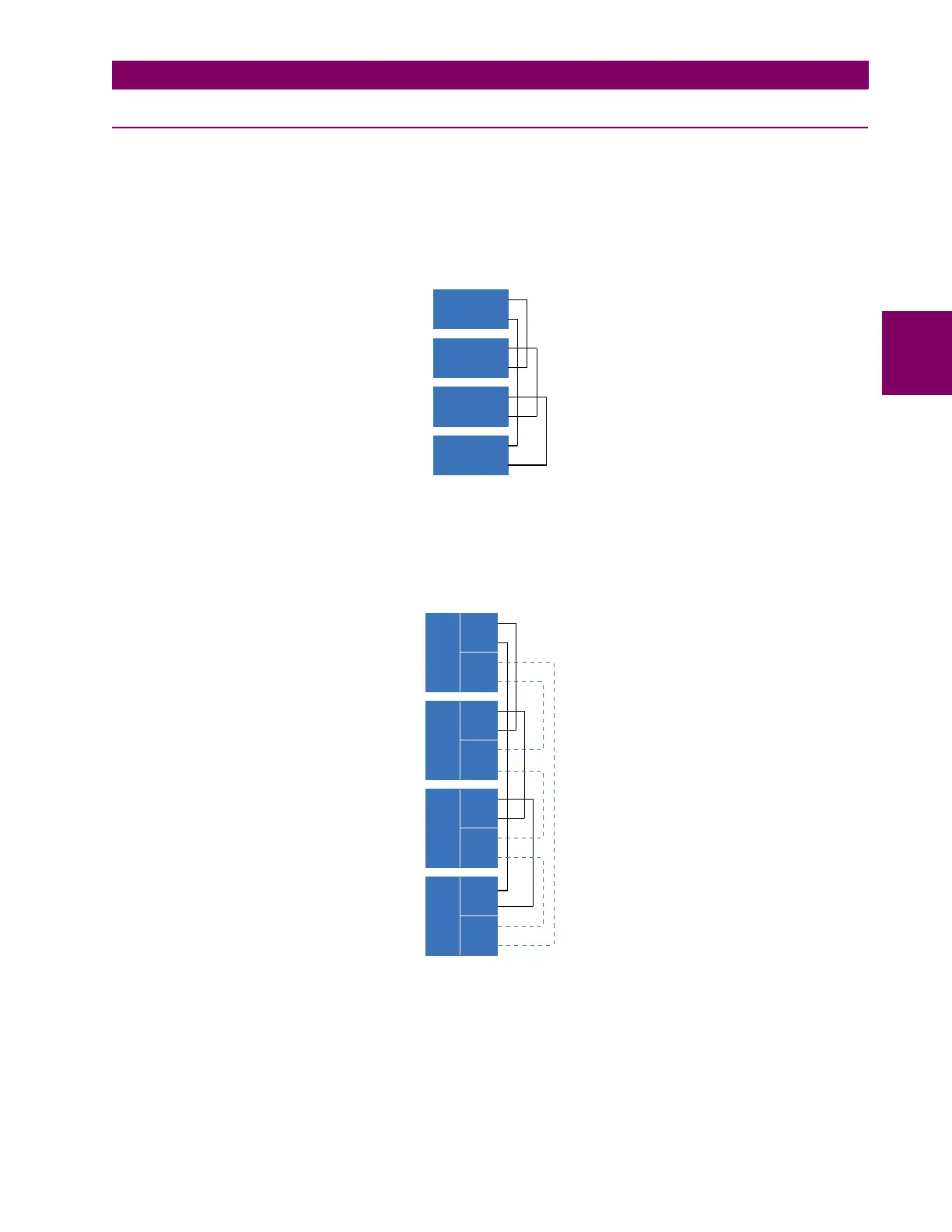
The interconnection for dual-channel type 7 communications modules is shown as follows. Two channel modules allow for
a redundant ring configuration. That is, two rings can be created to provide an additional independent data path. The
required connections are: UR1-Tx1 to UR2-Rx1, UR2-Tx1 to UR3-Rx1, UR3-Tx1 to UR4-Rx1, and UR4-Tx1 to UR1-Rx1
for the first ring; and UR1-Tx2 to UR4-Rx2, UR4-Tx2 to UR3-Rx2, UR3-Tx2 to UR2-Rx2, and UR2-Tx2 to UR1-Rx2 for the
second ring.
Figure 3–27: DIRECT INPUT AND OUTPUT DUAL CHANNEL CONNECTION
The following diagram shows the connection for three UR-series relays using two independent communication channels.
UR1 and UR3 have single type 7 communication modules; UR2 has a dual-channel module. The two communication chan-
nels can be of different types, depending on the Type 7 modules used. To allow the direct input and output data to cross-
over from channel 1 to channel 2 on UR2, the
DIRECT I/O CHANNEL CROSSOVER setting should be “Enabled” on UR2. This
forces UR2 to forward messages received on Rx1 out Tx2, and messages received on Rx2 out Tx1.
842006A2.CDR
Tx
Tx
Tx
Tx
UR 1
UR 2
UR 3
UR 4
Rx
Rx
Rx
Rx
842007A3.CDR
Tx1
UR 1
Tx2
Rx1
Rx2
Tx1
UR 2
Tx2
Rx1
Rx2
Tx1
UR 3
Tx2
Rx1
Rx2
Tx1
UR 4
Tx2
Rx1
Rx2
 Loading...


