5-324 T60 Transformer Protection System GE Multilin
5.8 INPUTS AND OUTPUTS 5 SETTINGS
5
Setting the TELEPROT INPUT ~~ DEFAULT setting to “On” defaults the input to logic 1 when the channel fails. A value of “Off”
defaults the input to logic 0 when the channel fails.
The “Latest/On” and “Latest/Off” values freeze the input in case of lost communications. If the latest state is not known,
such as after relay power-up but before the first communication exchange, then the input defaults to logic 1 for “Latest/On”
and logic 0 for “Latest/Off”.
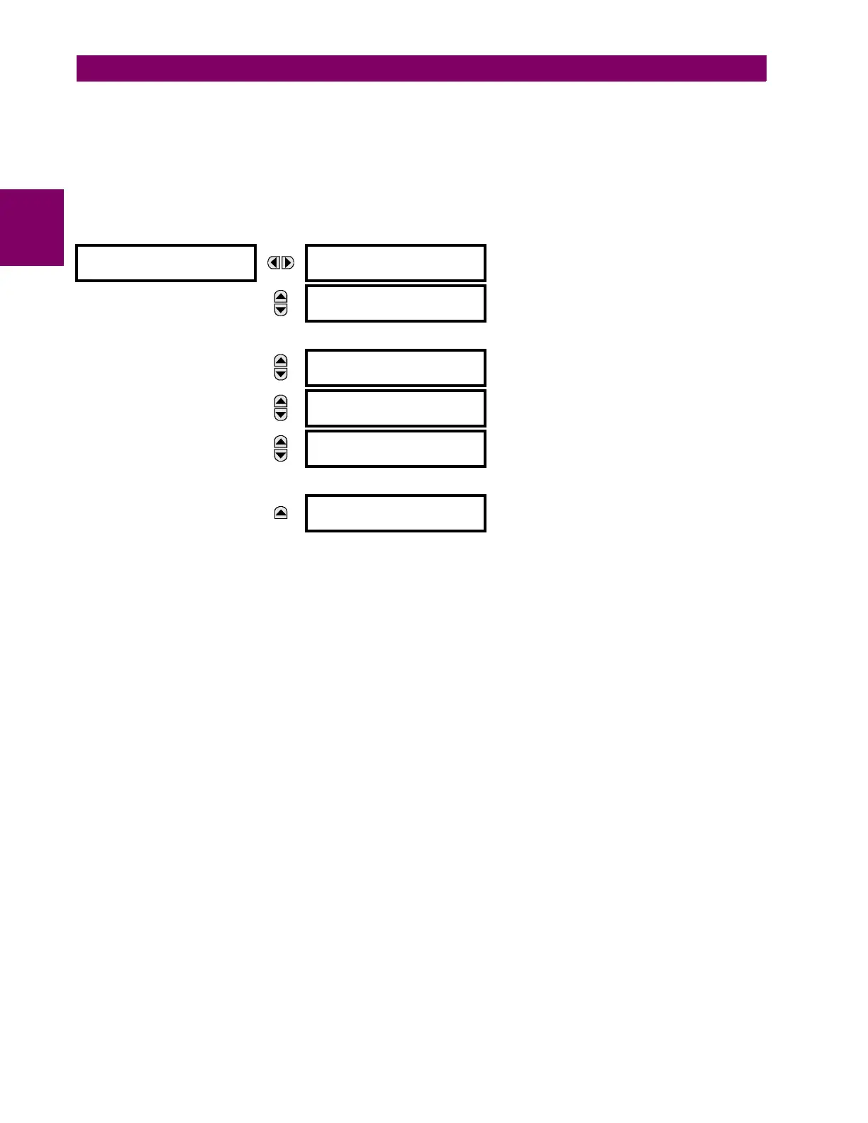
c) TELEPROTECTION OUTPUTS
PATH: SETTINGS INPUTS/OUTPUTS TELEPROTECTION TELEPROT OUTPUTS
As the following figure demonstrates, processing of the teleprotection inputs/outputs is dependent on the number of com-
munication channels and terminals. On two-terminal two-channel systems, they are processed continuously on each chan-
nel and mapped separately per channel. Therefore, to achieve redundancy, the user must assign the same operand on
both channels (teleprotection outputs at the sending end or corresponding teleprotection inputs at the receiving end). On
three-terminal two-channel systems, redundancy is achieved by programming signal re-transmittal in the case of channel
failure between any pair of relays.
TELEPROT OUTPUTS
TELEPROT OUTPUT 1-1:
Off
Range: FlexLogic operand
MESSAGE
TELEPROT OUTPUT 1-2:
Off
Range: FlexLogic operand
MESSAGE
TELEPROT OUTPUT 1-16:
Off
Range: FlexLogic operand
MESSAGE
TELEPROT OUTPUT 2-1:
Off
Range: FlexLogic operand
MESSAGE
TELEPROT OUTPUT 2-2:
Off
Range: FlexLogic operand
MESSAGE
TELEPROT OUTPUT 2-16:
Off
Range: FlexLogic operand

 Loading...


