GE Multilin T60 Transformer Protection System 5-215
5 SETTINGS 5.6 GROUPED ELEMENTS
5
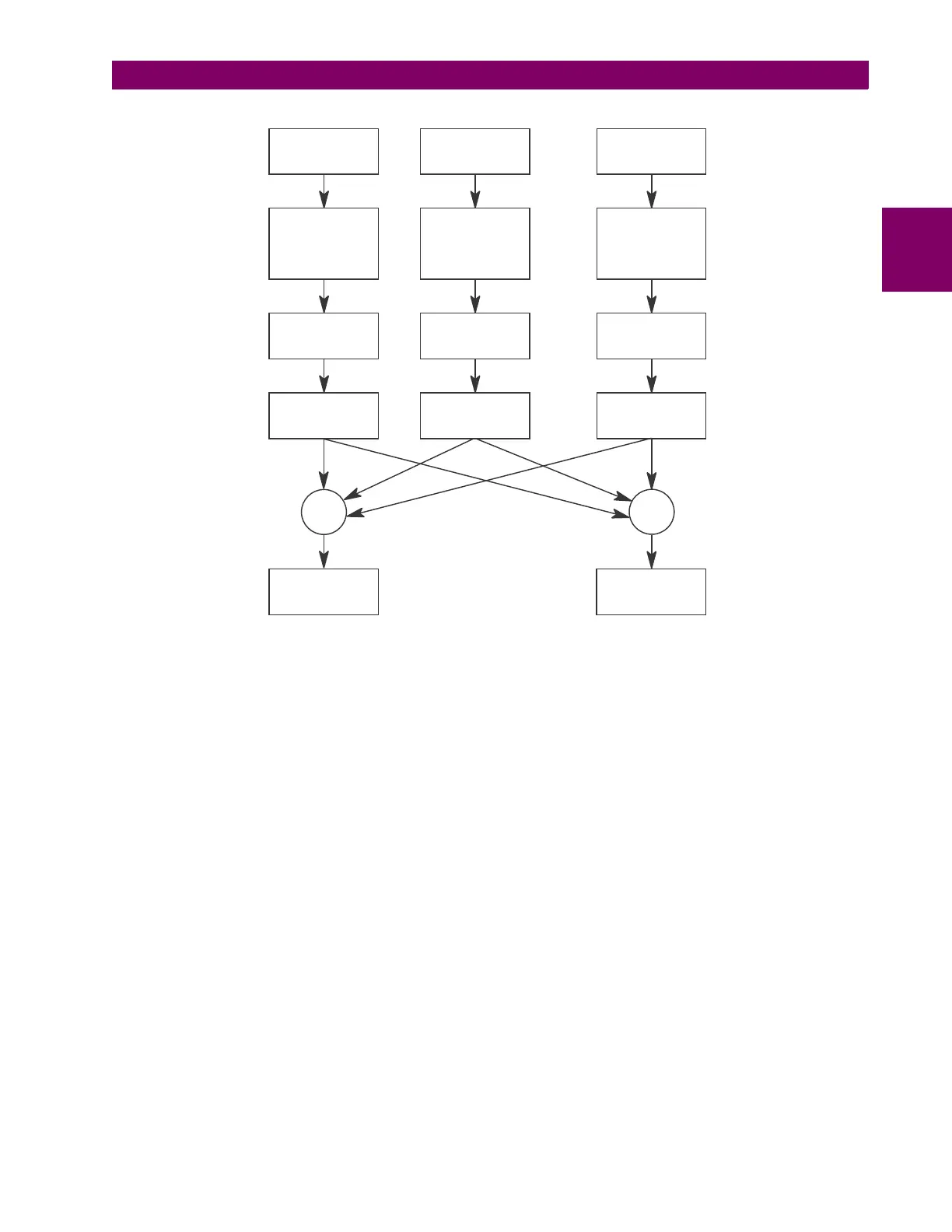
Figure 5–99: PERCENT DIFFERENTIAL CALCULATIONS
The T60 percent differential element is based on a configurable dual-breakpoint / dual-slope differential restraint character-
istic. The purpose of the preset characteristic is to define the differential restraint ratio for the transformer winding currents
at different loading conditions and distinguish between external and internal faults. Differential restraint ratio variations
occur due to current unbalance between primary and secondary windings and can be caused by the following:
1. Inherent CT inaccuracies
2. Onload tap changer operation: it adjusts the transformer ratio and consequently the winding currents
3. CT saturation
...
∑
Winding 1
current
waveform
Winding 2
current
waveform
Winding ‘n’
current
waveform
Magnitude
phase angle, and
zero sequence
compensation
(as required)
Magnitude
phase angle, and
zero sequence
compensation
(as required)
Magnitude
phase angle, and
zero sequence
compensation
(as required)
Decaying dc
offset filter
Decaying dc
offset filter
Decaying dc
offset filter
Discrete Fourier
Transform
MAX
Differential
phasor
Discrete Fourier
Transform
Discrete Fourier
Transform
Restraint
phasor
828714A1.CDR

 Loading...


