GE Multilin T60 Transformer Protection System 5-265
5 SETTINGS 5.6 GROUPED ELEMENTS
5
g) VOLTS PER HERTZ (ANSI 24, IEC PVPH)
PATH: SETTINGS GROUPED ELEMENTS SETTING GROUP 1(6) VOLTAGE ELEMENTS VOLTS/HZ 1(2)
The per-unit volts-per-hertz (V/Hz) value is calculated using the maximum of the three-phase voltage inputs or the auxiliary
voltage channel Vx input, if the source is not configured with phase voltages. To use the V/Hz element with auxiliary volt-
age, set SYSTEM SETUP SIGNAL SOURCES SOURCE 1(6) SOURCE 1(6) PHASE VT to “None” and SOURCE 1(6) AUX VT
to the corresponding voltage input bank. If there is no voltage on the relay terminals in either case, the per-unit V/Hz value
is automatically set to “0”. The per unit value is established as per voltage and nominal frequency power system settings as
follows:
1. If the phase voltage inputs defined in the source menu are used for V/Hz operation, then “1 pu” is the selected SYSTEM
SETUP AC INPUTS VOLTAGE BANK N PHASE VT N SECONDARY setting, divided by the divided by the SYSTEM
SETUP
POWER SYSTEM NOMINAL FREQUENCY setting.
2. If the voltage bank connection value is selected as “Delta”, then the phase-to-phase nominal voltage is used to define
the per-unit value. If the voltage bank connection value is selected as “Wye”, then the VOLTS/HZ 1 VOLTAGE MODE set-
ting further defines the operating quantity and per-unit value for this element. If the voltage mode is set as “Phase-
phase”, then the operating quantity for this element will be phase-to-phase nominal voltage. Likewise, if the voltage
mode is set to “Phase-ground”, then the operating quantity for this element will be the phase-to-ground nominal volt-
age. It is beneficial to use the phase-to-phase voltage mode for this element when the T60 device is applied on an iso-
lated or resistance-grounded system.
3. When the auxiliary voltage Vx is used (regarding the condition for “None” phase voltage setting mentioned above),
then the 1 pu value is the
SYSTEM SETUP AC INPUTS VOLTAGE BANK N AUXILIARY VT N SECONDARY setting
divided by the
SYSTEM SETUP POWER SYSTEM NOMINAL FREQUENCY setting.
4. If V/Hz source is configured with both phase and auxiliary voltages, the maximum phase among the three voltage
channels at any given point in time is the input voltage signal for element operation, and therefore the per-unit value
will be calculated as described in Step 1 above. If the measured voltage of all three phase voltages is 0, than the per-
unit value becomes automatically 0 regardless of the presence of auxiliary voltage.
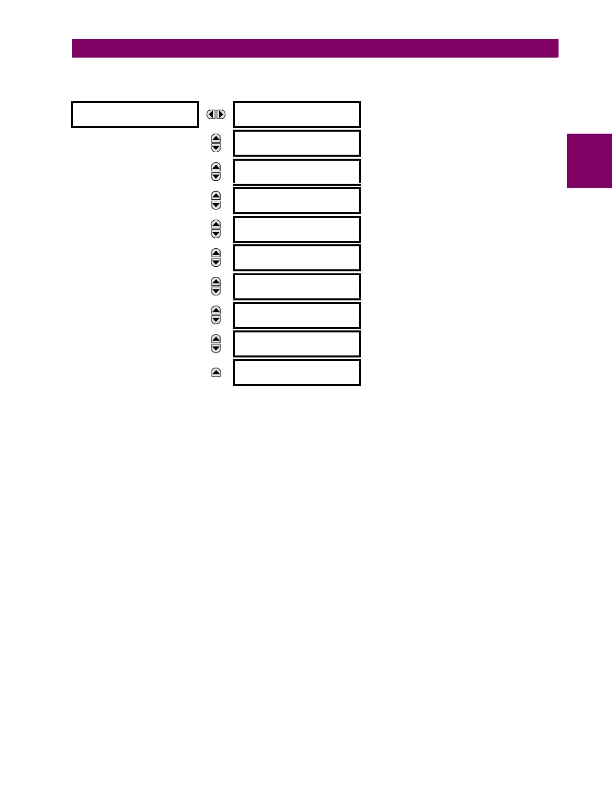
VOLTS/HZ 1
VOLTS/HZ 1 FUNCTION:
Disabled
Range: Disabled, Enabled
MESSAGE
VOLTS/HZ 1 SOURCE:
SRC 1
Range: SRC 1, SRC 2, SRC 3, SRC 4, SRC 5, SRC 6
MESSAGE
VOLTS/HZ 1 VOLTAGE:
MODE: Phase-ground
Range: Phase-ground, Phase-phase
MESSAGE
VOLTS/HZ 1 PICKUP:
1.00 pu
Range: 0.80 to 4.00 pu in steps of 0.01
MESSAGE
VOLTS/HZ 1 CURVE:
Definite Time
Range: Definite Time, Inverse A, Inverse B, Inverse C,
FlexCurve A, FlexCurve B, FlexCurve C,
FlexCurve D
MESSAGE
VOLTS/HZ 1 TD
MULTIPLIER: 1.00
Range: 0.05 to 600.00 in steps of 0.01
MESSAGE
VOLTS/HZ 1
T-RESET: 1.0 s
Range: 0.0 to 1000.0 s in steps of 0.1
MESSAGE
VOLTS/HZ 1 BLOCK:
Off
Range: FlexLogic operand
MESSAGE
VOLTS/HZ 1 TARGET:
Self-reset
Range: Self-reset, Latched, Disabled
MESSAGE
VOLTS/HZ 1 EVENTS:
Disabled
Range: Disabled, Enabled
 Loading...


