GE Multilin T60 Transformer Protection System 5-277
5 SETTINGS 5.7 CONTROL ELEMENTS
5
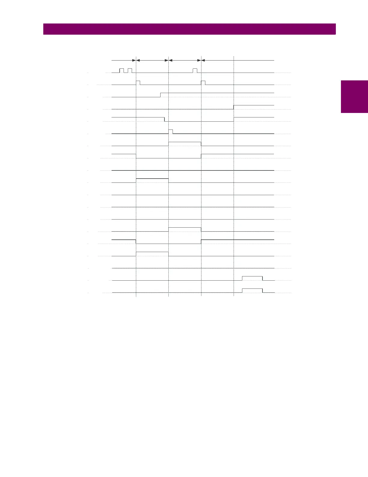
Figure 5–139: ACKNOWLEDGE MODE
APPLICATION EXAMPLE
Consider an application where the selector switch is used to control setting groups 1 through 4 in the relay. The setting
groups are to be controlled from both user-programmable pushbutton 1 and from an external device via contact inputs 1
through 3. The active setting group shall be available as an encoded three-bit word to the external device and SCADA via
output contacts 1 through 3. The pre-selected setting group shall be applied automatically after 5 seconds of inactivity of
the control inputs. When the relay powers up, it should synchronize the setting group to the three-bit control input.
Make the following changes to setting group control in the
SETTINGS CONTROL ELEMENTS SETTING GROUPS menu:
SETTING GROUPS FUNCTION: “Enabled” GROUP 4 ACTIVATE ON: “SELECTOR 1 POS 4"
SETTING GROUPS BLK: “Off” GROUP 5 ACTIVATE ON: “Off”
GROUP 2 ACTIVATE ON: “SELECTOR 1 POS 2" GROUP 6 ACTIVATE ON: “Off”
GROUP 3 ACTIVATE ON: “SELECTOR 1 POS 3"
Make the following changes to selector switch element in the
SETTINGS CONTROL ELEMENTS SELECTOR SWITCH
SELECTOR SWITCH 1 menu to assign control to user programmable pushbutton 1 and contact inputs 1 through 3:
842736A1.CDR
STEP-UP
ACK
3BIT A0
3BIT A1
3BIT A2
3BIT ACK
POS 1
POS 2
POS 3
POS 4
POS 5
POS 6
POS 7
BIT 0
BIT 1
BIT 2
pre-existing
position 2
changed to 4 with
a pushbutton
changed to 1 with
a 3-bit input
changed to 2 with
a pushbutton
STP ALARM
BIT ALARM
ALARM
 Loading...


