5-282 T60 Transformer Protection System GE Multilin
5.7 CONTROL ELEMENTS 5 SETTINGS
5
• FREQ RATE 1 MIN FREQUENCY: This setting defines minimum frequency level required for operation of the element.
The setting may be used to effectively block the feature based on frequency. For example, if the intent is to monitor an
increasing trend but only if the frequency is already above certain level, this setting should be set to the required fre-
quency level.
• FREQ RATE 1 MAX FREQUENCY: This setting defines maximum frequency level required for operation of the ele-
ment. The setting may be used to effectively block the feature based on frequency. For example, if the intent is to mon-
itor a decreasing trend but only if the frequency is already below certain level (such as for load shedding), this setting
should be set to the required frequency level.
If the signal source assigned to the frequency rate of change element is only set to auxiliary VT, then the minimum
voltage supervision is 3 V.
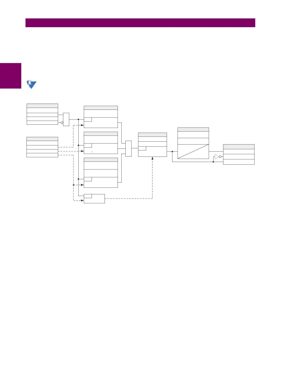
Figure 5–143: FREQUENCY RATE OF CHANGE SCHEME LOGIC
|V_1 |>PICKUP
FREQ RATE 1 BLOCK:
Off
RUN
FREQ RATE 1 SOURCE:
Pos seq voltage (V_1)
FREQ RATE 1 FUNCTION:
SETTINGS
Enabled = 1
Pos seq current (I_1)
Frequency (F)
AND
FREQ RATE 1OV SUPV
PICKUP:
SETTING
SETTING
|I_1 |>P ICKUP
RUN
FREQ RATE 1OCSUPV
PICKUP:
SETTING
F>MIN & F < MAX
RUN
FREQ RATE 1MIN
FREQUENCY:
SETTINGS
FREQ RATE 1MAX
FREQUENCY:
AND
Calculate df/dt
RUN
df/dt > PICKUP
RUN
SETTINGS
FREQ RATE 1PICKUP:
FREQ RATE 1TREND:
FLEXLOGIC OPERANDS
FREQ RATE 1DPO
FREQ RATE 1OP
FREQ RATE 1 PKP
FREQ RATE 1RESET
DELAY:
SETTINGS
FREQ RATE 1PICKUP
DELAY:
t
PKP
t
RST
832023A2.CDR
 Loading...


