5-304 T60 Transformer Protection System GE Multilin
5.7 CONTROL ELEMENTS 5 SETTINGS
5
The CT failure logic (see below) is based on the presence of the zero-sequence current in the supervised CT source and
the absence of one of three or all of the three following conditions.
1. Zero-sequence current at different source current (may be different set of CTs or different CT core of the same CT).
2. Zero-sequence voltage at the assigned source.
3. Appropriate protection element or remote signal.
The CT failure settings are described below.
• CT FAIL FUNCTION: This setting enables or disables operation of the CT failure element.
• CT FAIL BLOCK: This setting selects a FlexLogic operand to block operation of the element during some condition
(for example, an open pole in process of the single pole tripping-reclosing) when CT fail should be blocked. Local sig-
nals or remote signals representing operation of some remote current protection elements via communication chan-
nels can also be chosen.
• CT FAIL 3I0 INPUT 1: This setting selects the current source for input 1. The most critical protection element should
also be assigned to the same source.
• CT FAIL 3I0 INPUT 1 PICKUP: This setting selects the 3I_0 pickup value for input 1 (the main supervised CT source).
• CT FAIL 3I0 INPUT 2: This setting selects the current source for input 2. Input 2 should use a different set of CTs or a
different CT core of the same CT. If 3I_0 does not exist at source 2, then a CT failure is declared.
• CT FAIL 3I0 INPUT 2 PICKUP: This setting selects the 3I_0 pickup value for input 2 (different CT input) of the relay.
• CT FAIL 3V0 INPUT: This setting selects the voltage source.
• CT FAIL 3V0 INPUT PICKUP: This setting specifies the pickup value for the 3V_0 source.
• CT FAIL PICKUP DELAY: This setting specifies the pickup delay of the CT failure element.
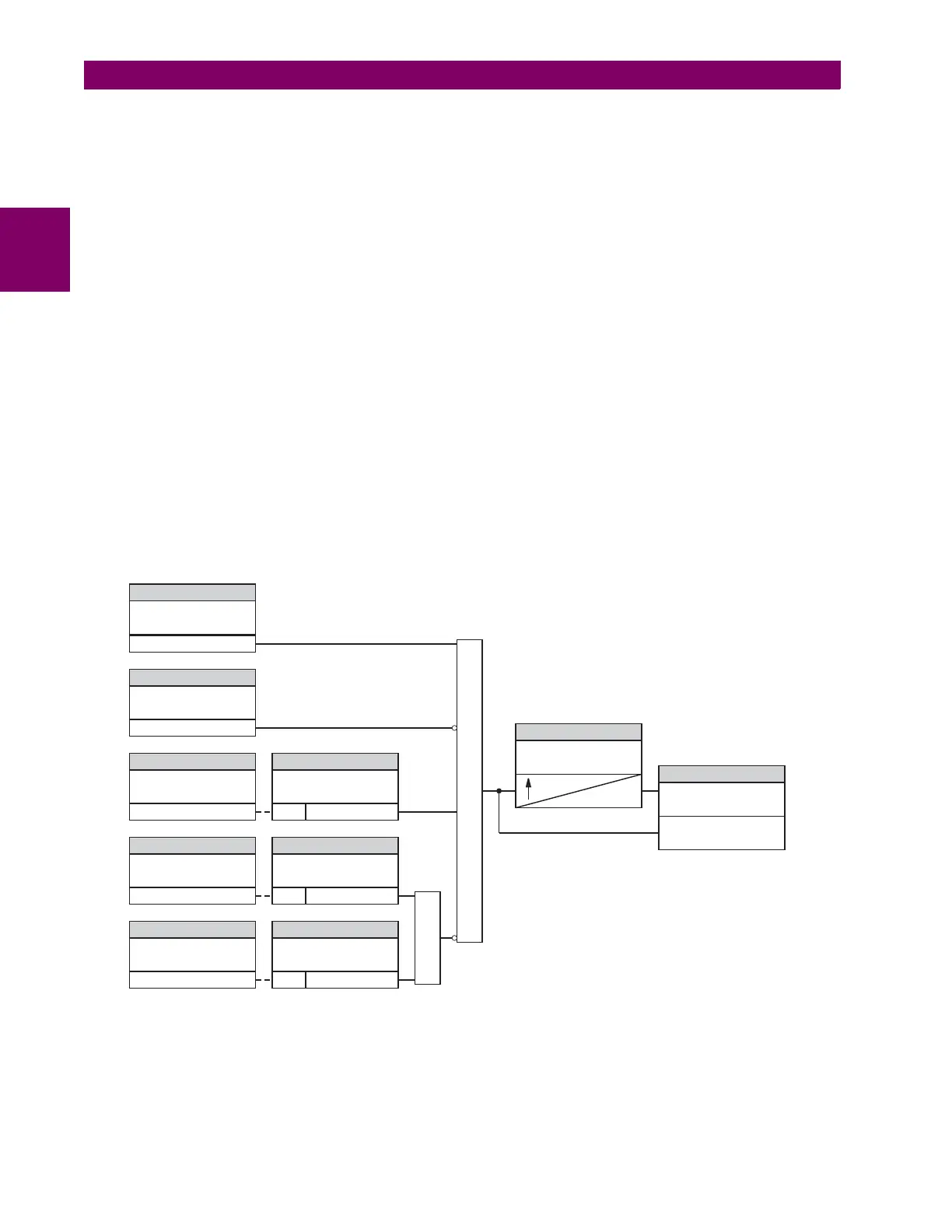
Figure 5–155: CT FAILURE DETECTOR SCHEME LOGIC
CT FAIL FUNCTION:
CT FAIL BLOCK:
CT FAIL 3IO INPUT1: CT FAIL 3IO INPUT1 PKP:
CT FAIL 3VO INPUT: CT FAIL 3VO INPUT:
CT FAIL 3IO INPUT2: CT FAIL 3IO INPUT2 PKP:
CT FAIL PICKUP DELAY:
AND
OR
SETTING
Enabled=1
SETTING
SETTINGSETTING
SETTINGSETTING
SETTINGSETTING
SETTING
Off=0
SRC1 RUN 3IO > PICKUP
3IO > PICKUP
3VO > PICKUPSRC1 RUN
SRC2 RUN
FLEXLOGIC OPERANDS
CT FAIL OP
CT FAIL PKP
827048A7.CDR
0
 Loading...


