5-184 T60 Transformer Protection System GE Multilin
5.6 GROUPED ELEMENTS 5 SETTINGS
5
2. The MEMORY DURATION setting (common for the distance elements of all zones as entered under SETTINGS
GROUPED ELEMENTS SETTING GROUP 1(6) DISTANCE).
The common distance settings described earlier must be properly chosen for correct operation of the phase distance ele-
ments. Additional details may be found in chapter 8: Theory of operation.
Although all zones can be used as either instantaneous elements (pickup [PKP] and dropout [DPO] FlexLogic operands) or
time-delayed elements (operate [OP] FlexLogic operands), only zone 1 is intended for the instantaneous under-reaching
tripping mode.
Ensure that the Phase VT Secondary Voltage setting (see the SETTINGS SYSTEM SETUP AC
INPUTS VOLTAGE BANK menu) is set correctly to prevent improper operation of associated mem-
ory action.
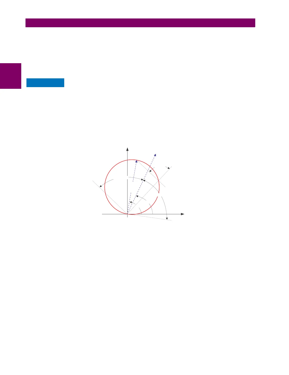
• PHS DIST Z1 DIR: All phase distance zones are reversible. The forward direction is defined by the PHS DIST Z1 RCA
setting, whereas the reverse direction is shifted 180° from that angle. The non-directional zone spans between the for-
ward reach impedance defined by the
PHS DIST Z1 REACH and PHS DIST Z1 RCA settings, and the reverse reach imped-
ance defined by PHS DIST Z1 REV REACH and PHS DIST Z1 REV REACH RCA as illustrated below.
• PHS DIST Z1 SHAPE: This setting selects the shape of the phase distance function between the mho and quadrilat-
eral characteristics. The selection is available on a per-zone basis. The two characteristics and their possible varia-
tions are shown in the following figures.
Figure 5–71: DIRECTIONAL MHO DISTANCE CHARACTERISTIC
837720A1.CDR
X
R
REACH
RCA
DIR RCA
DIR COMP LIMIT
DIR COMP LIMIT
COMP LIMIT

 Loading...


