8-4 T60 Transformer Protection System GE Multilin
8.2 DIFFERENTIAL CHARACTERISTIC TEST EXAMPLES 8 COMMISSIONING
8
8.2.2 TEST EXAMPLE 1
a) DESCRIPTION
TRANSFORMER DATA:
• 20 MVA, 115/12.47 kV, CT (HV) = 200:1, CT (LV) = 1000:1, Y/y0° with a grounded LV neutral
TEST SET CONFIGURATION:
The fault current distribution for an external b-c fault is identical for the HV and LV transformer sides and can be simulated
easily with two current sources. Connect the first current source to the relay Phase “B” and “C” terminals, corresponding to
the HV winding CTs in series, and the second source to the Phase “b” and “c” relay terminals, corresponding to the LV CTs.
Ensure the polarity is correct and the relative phase angles are similar to the shown in the figure; that is, 180° between IB
and IC, 180° between Ib and Ic, 180° between IB and Ib, and 180° between IC and Ic. Follow the magnitudes and angles of
the injected currents from the tables below to ensure the test will be performed correctly
OPERATING CRITERIA:
The differential element operates if the differential current (I
d
) exceeds the characteristic defined by the relay settings for
restraint current magnitude (I
r
). The differential current I
d
is the vector sum of the compensated currents, and I
r
is the larg-
est compensated current. Compensation refers to vector and magnitude corrections applied to the currents from the HV
and LV transformer sides.
The tests verify the operation and no-operation response for points from all regions of the percentage differential character-
istic. These tests are:
• Test for zero differential current
• Minimum Pickup
•Slope 1
• The region between Slope 1 and Slope 2
•Slope 2
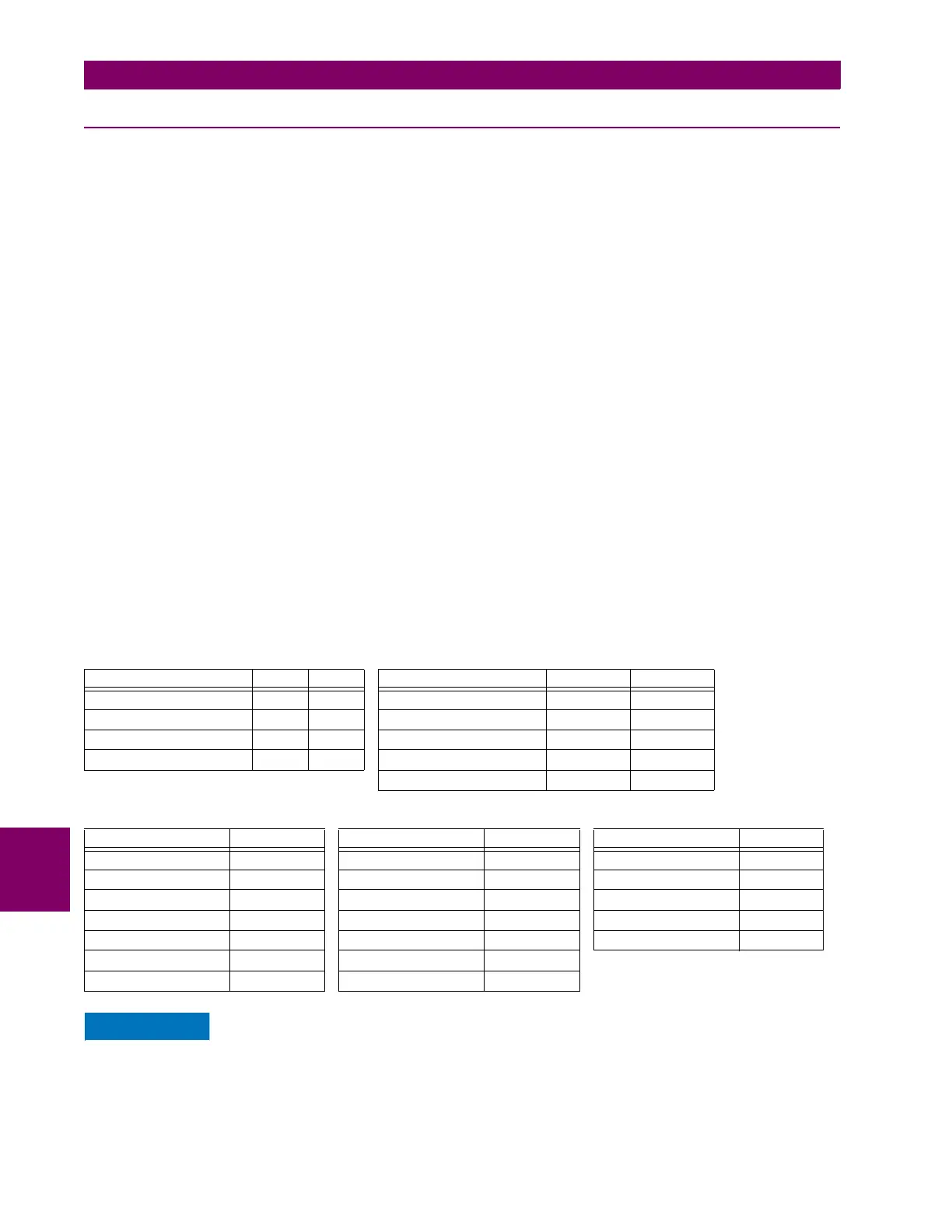
RELAY CONFIGURATION:
The AC Inputs and Source are configured as follows:
TWO WINDING TRANSFORMER CONFIGURATION:
Application of excessive current (> 3 ´ In) for extended periods damages the relay.
AC INPUTS SETTING CT F1 CT M1 SOURCE SETTING SOURCE 1 SOURCE 2
Phase CT Primary 200 1000 Name SRC 1 SRC 2
Phase CT Secondary 1 1 Phase CT F1 M1
Ground CT Primary X X Ground CT X X
Ground CT Secondary X X Phase VT X X
Aux VT X X
WINDING 1 SETTINGS VALUE WINDING 2 SETTINGS VALUE PERCENT DIFF VALUE
Source SRC 1 Source SRC 2 Minimum PKP 0.1 pu
Rated MVA 20 MVA Rated MVA 20 MVA Slope 1 15%
Nom Ph-Ph Voltage 115 kV Nom Ph-Ph Voltage 12.47 kV Breakpoint 1 2 pu
Connection Wye Connection Wye Breakpoint 2 8 pu
Grounding Not within zone Grounding Within zone Slope 2 95%
Angle WRT 0° Angle WRT 0°
Resistance 3Ph 10.000 ohms Resistance 3Ph 10.000 ohms
 Loading...


