6-26 T60 Transformer Protection System GE Multilin
6.3 METERING 6 ACTUAL VALUES
6
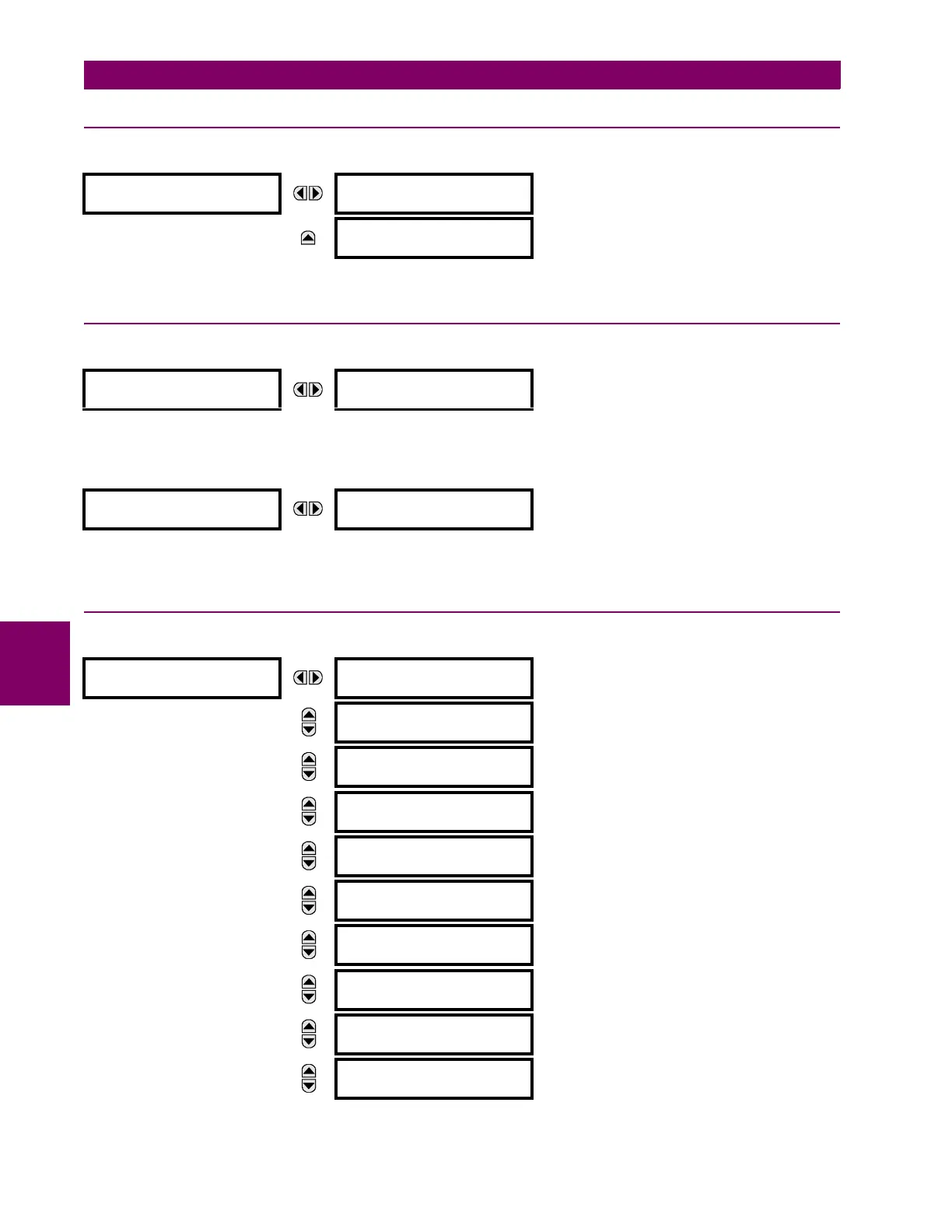
6.3.12 RESTRICTED GROUND FAULT
PATH: ACTUAL VALUES METERING RESTRICTED GROUND FAULT CURRENTS RESTRICTED GROUND FAULT 1(4)
The differential and restraint current values for the restricted ground fault element are displayed in this menu.
6.3.13 TRANSDUCER INPUTS AND OUTPUTS
PATH: ACTUAL VALUES METERING TRANSDUCER I/O DCMA INPUTS DCMA INPUT xx
Actual values for each dcmA input channel that is enabled are displayed with the top line as the programmed channel ID
and the bottom line as the value followed by the programmed units.
PATH: ACTUAL VALUES METERING TRANSDUCER I/O RTD INPUTS RTD INPUT xx
Actual values for each RTD input channel that is enabled are displayed with the top line as the programmed channel ID and
the bottom line as the value.
6.3.14 DISTANCE
PATH: ACTUAL VALUES METERING DISTANCE
RESTRICTED
GROUND FAULT 1
RGF 1 DIFF Igd:
0.000 A
MESSAGE
RGF 1 RESTR Igr:
0.000 A
DCMA INPUT xx
DCMA INPUT xx
0.000 mA
RTD INPUT xx
RTD INPUT xx
-50 °C
DISTANCE
AB LOOP RESISTANCE
RAB: 0.00 Ohms
MESSAGE
AB LOOP REACTANCE
XAB: 0.00 Ohms
MESSAGE
AB LOOP IMPEDANCE
ZAB: 0.00 Ohms
MESSAGE
AB LOOP IMPEDANCE
ANGLE: 0.00 DEG
MESSAGE
BC LOOP RESISTANCE
RBC: 0.00 Ohms
MESSAGE
BC LOOP REACTANCE
XBC: 0.00 Ohms
MESSAGE
BC LOOP IMPEDANCE
ZBC: 0.00 Ohms
MESSAGE
BC LOOP IMPEDANCE
ANGLE: 0.00 DEG
MESSAGE
CA LOOP RESISTANCE
RCA: 0.00 Ohms
MESSAGE
CA LOOP REACTANCE
XCA: 0.00 Ohms
 Loading...


